|
Introduction
Have you ever wondered how the air
suspension on your Mark VIII works? Have you
ever wanted to be able to manually
manipulate the system and adjust ride height
at will? Have you ever jacked up your Mark
with the air-ride switch on, only to find
out that you couldn't get the jack back out
from under the car when you let it back
down? Better yet, do you want to SLAM
your Mark? If you answered yes to any of
these questions, then you have come to the
right place! If you answered no, or are too
scared to tamper with the system, click
HERE!
This is the perfect place for people like me
who love to build things, take things apart,
break stuff and just overall destroy
something that used to work. Ha,Ha.
Actually, most of that is true, but the main
challenge for designers and artists,
engineers and planners is to design
something that is USEFUL.(ok, maybe not
artists). Being able to have usefulness and
practicality are the key goals. That was my
original idea when designing this system. It
had to be useful and easy to operate.
Further more, it had to be easy to install.
Needless to say, I believe I have achieved
these goals. Granted, a certain amount of
expertise is required to install the system,
but I do not place that knowledge and
ability out of the realm of the common do it
yourselfer.
The knowledge presented in the following
paragraphs represents the blood, sweat, and
beers that were weathered over countess
months of research and development. Detailed
air-suspension information is only available
through the factory service manuals, which
might I add, are well worth the price just
for the suspension information. I want to
encourage anyone who performs this
modification to go out and buy a service
manual; not just for the information, but
because you owe it to yourself to support
the company from which you acquired the
information. Well actually, from which I
acquired the info and gave it to you. You
can get them through
Ebay, or at Helm Inc. I used a 1994
Service Manual, and a1993 Electrical &
Vacuum Troubleshooting Manual (EVTM). The
EVTM is good for describing HOW the circuit
works, not just troubleshooting and
schematics. It is the manual that I based
almost everything in this system around.
Enough BS, it's time to get started.
OVERVIEW
The following is a list of instructions for
lowering a 1993 Lincoln Mark VIII. Wiring
schematics and colors are the same on both
1993 and 1998 schematics I compared. To
better understand the logic behind the
instructions, I recommend reading the next
section which explains how it works. There
are also some special considerations and/or
limitations to the system which MUST be read
prior to installing anything. Please scroll
all the way to the bottom of this page to
read the considerations. Removing the
console, accessing the computer, tapping the
wires, and putting it all back together
should take around three hours. Fabricating
the switch panel should take an hour or so.
Be patient and if you are short on
something, take the time to either buy more
supplies or find the right tool. All
modifications are done at your own risk.
HOW IT
WORKS
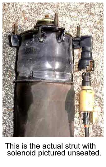
This section will briefly explain the
air-suspension on the Mark VIII. There are
two air struts up front that look like
conventional McPherson struts with huge
airbags wrapped around them instead of
springs. The rears are simply bags. There is
a solenoid mounted to the top of them that
allows air to pass through when opened. The
solenoid opens when energized. There is also
a vent solenoid in the air compressor. This
solenoid must open when any vent process is
initiated and it must be closed when raising
the car. The custom set-up that I designed
energizes these five solenoids to lower the
vehicle. Not exactly rocket science. There
are also three height sensors that send a
voltage signal back to the air suspension
computer. Additionally, there are other
sensors the computer uses such as vehicle
speed, braking sensors, steering, etc. The
computer processes this information and uses
it to make height corrections and other
adjustments.
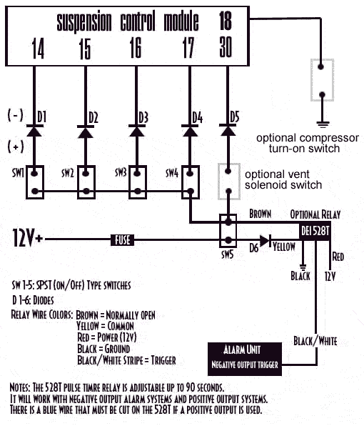
SOLENOID
SYSTEM OPERATION
After completeing this modification, you
will be able to press a button on your
transmitter and lower the car to a desired
height. When the car is started again, the
stock system will sense that the car is low
and start to raise the car, first the front,
then the rear. If you install the necessary
switches required for raising the car, you
will be able to raise the car as well. This
might be useful on camping trips, outdoor
ventures, or just going through a car wash.
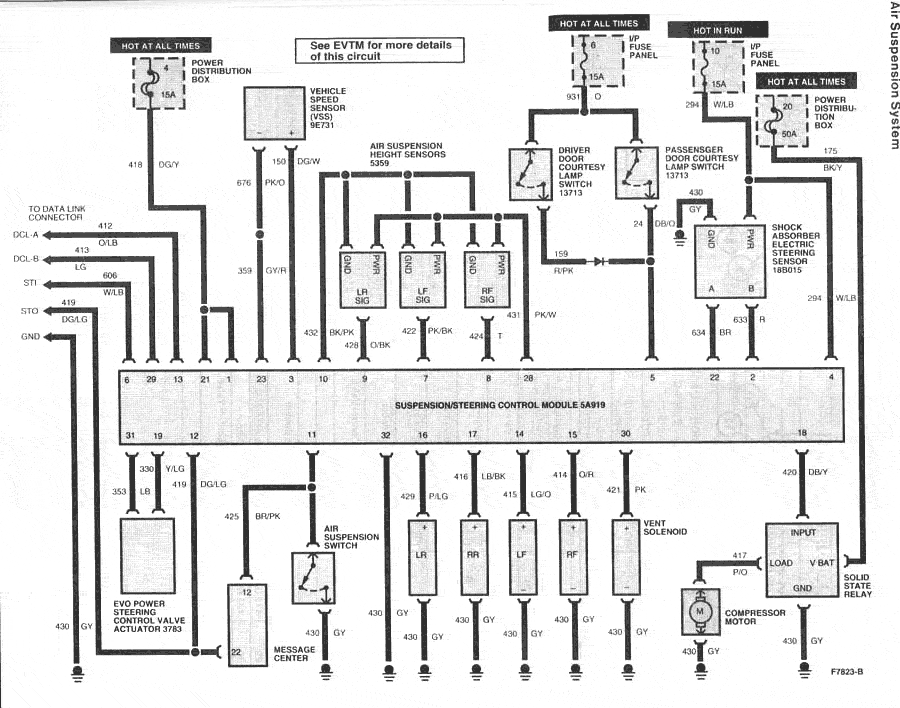
SCHEMATICS
TOOLS
|
Drill and ¼" bit
Jigsaw and blade
Solderless Connector Crimping Tool
Small File
Multimeter |
Belt Sander
Phillips Screwdriver
9/32 socket and drive
6 inch and 3 inch extensions
Wire Stripper |
SUPPLIES
|
6-Doides
6-SPST switches
30 Feet Speaker
5 Red Female Spade Connectors
14 Red Butt Connectors
2 Yellow Butt Connectors |
2 Fuse Holders and Fuse
Electrical Tape
Wire 5 Wire Splices
5 Yellow Female Spade Connectors
1-6"x6" Sheet of Plastic
Various Nylon Ties |
It doesn't hurt to have extras!
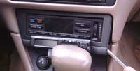
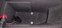
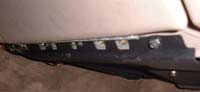
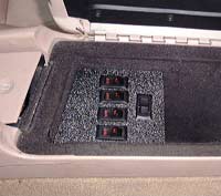
CONSOLE
REMOVAL
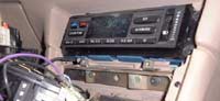
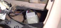
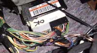
ACCESSING THE AIR-SUSPENSION ECU
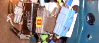
WIRING THE SYSTEM
Once you have removed the console and gained
access to the EVO/Air Suspension Computer,
it's time to tap the wires and route them
into the console glovebox. Use extra care
not to pull the wires and force one out of
its connector. Make sure to mark which wires
are front/rear, left/right. The speaker wire
comes in handy here since they are already
paired and one is striped. Keep the striped
wire dedicated to either left or right for
both front and rear. I placed a black piece
of electrical tape near the end of the rear
pair to differentiate it from the front. For
the compressor vent solenoid, use a
different type of wire altogether, or
differentiate it in some way from the
others. Once spliced, wrap electrical tape
around the wire bundle as it leads to the
console. This is not necessary, but it makes
for a cleaner, more OEM look. You can tap
into terminal 21 on the black connector for
your 12v supply, or you can run a separate
wire to the battery. Remember to fuse this
lead, and make the fuse easily accessible. I
tapped into the 8-gauge power wire running
back to my amp. This allowed me to locate
the fuse in the console glovebox. Now that
you have the wires spliced and routed, run
them through the small opening in the front
(towards the dash) of the glovebox and start
crimping. First the diodes, then the
terminal connectors. Place a strip of
electrical tape over any exposed metal leads
on the diodes to ensure they don't touch one
another. Plug everything in and test the
system before you button 'er up. When
connecting the switches, make sure you will
be able to get them back off. Some of them
are a tight fit. I ripped a couple of wires
out of their connectors trying to unplug
them from the switches. If all is well, you
are past the worst, and the rest is all
downhill!
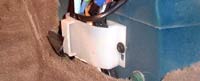
FABRICATING THE SWITCH PANEL
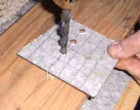
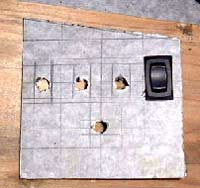
First, make a rough cardboard template to
get an idea of what you need, then trace it
onto the plastic. Next, cut out a rough
rendition with the jigsaw and from there use
a belt sander to make minor adjustments
until you get the perfect fit. Now that it
fits, you're ready to prepare the holes for
the switches. The eyeball will suffice, but
feel free to use whatever means you feel
necessary to accomplish this task. Drill
five (or six*) holes and enlarge them until
the switches fit snugly. This is where it
helps to have switches with a lot of
overlap; it makes it easier to make it look
nice. That's it, you're done! That wasn't so
bad after all, was it?
RAISING
THE VEHICLE
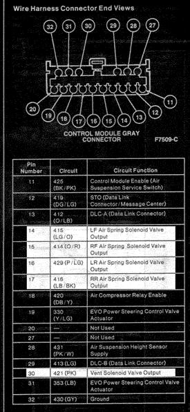
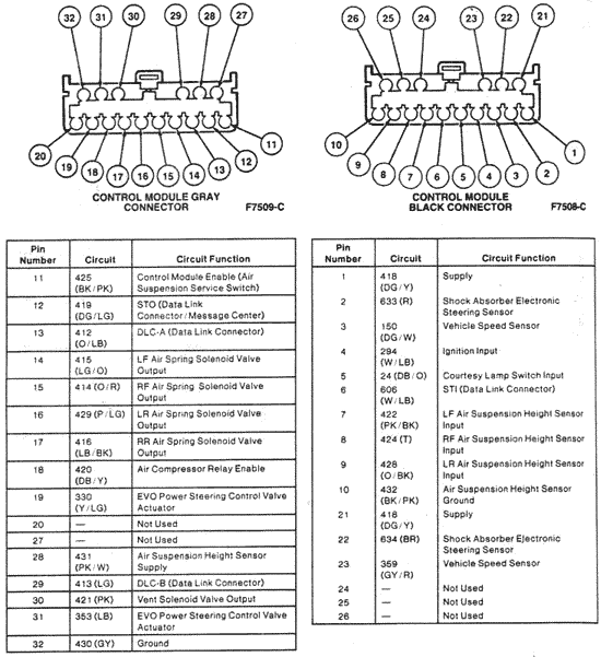
To raise the vehicle, circuit 420 (pin 18 in
the gray connector) must be grounded. This
tells the compressor relay to turn on the
compressor. To let air into the struts, open
the associated solenoid(s) while the
compressor is running. When the desired
height is reached, close the solenoids. The
stock system does the front and rear
separately. I would imagine trying to do all
four corners at once would create an
unwelcome "strain" on the compressor. There
is also a one second delay between the time
when the compressor starts, to when the
solenoids open. Additionally there is a
circuit breaker for overload protection.
SPECIAL CONSIDERATIONS
This is where I explain various aspects of
the system and how they work in the real
world, what to expect, what not to expect
and generally warn you that you might screw
something up! The first and foremost message
I have is:
DISCONNECT THE BATTERY WHENEVER YOU WORK
ON THE ELECTRICAL SYSTEM!
The second one is:
THE SYSTEM WAS NOT DESIGNED TO BE
OPERATED LIKE THIS.
YOU WILL BE CAUSING ADDITIONAL WEAR ON ALL
COMPONENTS!
While it was not designed with this in mind,
that's not saying that the system can't
handle it. Only time will tell. I have had
this system on for over a year (wow), and
nothing has "pooped out" yet. Be prepared if
something does go wrong. Know how to fix
your system. The parts are actually not that
expensive.
Arnott Industries sells front struts for
$145, and the rears for $85. A compressor
will run you $150 (as of 9-22-00). You can
also get them through Bagmaster USA,
although considerably more ($295-front, $180
rear), but less than the dealer price. The
Bagmaster compressor is $215. They seem
like a good company and have a
message board dedicated strictly to
Air-Suspension Problems, but I have noticed
some of their info has been inaccurate in
the past. They also were supposed to send me
some information, but never did. It may have
just been the associates I dealt with...( I
talked to two different people, with the
same results).
Now that I've said that, on to what you can
expect.
Depending on the way you wire the system,
the front will drop down first, then the
rear. In actuality, both ends are dropping
at the same time, its just that the rear
takes longer because it doesn't have a 32V
DOHC V8 to help it drop. This will create a
jacked up look for 60 seconds or so until
the rear reaches its resting place. You can
control the height of the rear by adjusting
the timer relay. You could wire it so that
it does the rear first then the front, but
that would necessitate more relays (or a
different, more expensive one), and
therefore extend costs. Dropping the rear,
then at the right time dropping the front
will essenstially make it seem like it is
dropping evenly. Numerous possibilties exist
with the implementation of sophistcated
relay circuits, but I have not yet
experimented with anything but a single DEI
528T ($25).
I designed this system primarily to be able
to drop the car all the way down to "pose"
on occasion. Not everyday, and for Gods
sakes, not to drive it like that. Please use
good judgement when implementing this
modification. The main drawback to this
sytem is rise time. Whenever you slam the
car, it will take a good 80-90 seconds to
get it back up to it's original position.
You can drive it sooner only if the rear is
not slammed. You just need 10-15 seconds to
get some travel in the front struts. As you
drive, it will pump back up. You obviously
would not want to do this whenever obstacles
need to be overcome. You can adjust the
height of the front and rear by using
multiple timer relays. One relay will
suffice for adjusting the rear so that it
does not lower too far.
I like to compare this modification to
Nitrous Oxide injection. Why? Because if you
have it, you are gonna use it. That means
hardcore guys like me will be dropping the
car beyond the sensor lowering height to get
that extra inch of drop. That being the
case, you will run into some "quirks", and
they are:
1) If you activate the system while the car
is running, you will recieve a check air
ride message.
2) You will not be able to raise the car
back up unless you turn it off, wait for 10
seconds, then turn it back on. This is
assuming you did not wire the raising
circuit.
3) If your car is sitting lower than the
sensor height, you must turn off the air
ride before you start the car to get it to
stay lowered. Afterwards, if you start the
car, drive down the road, then decide that
you want to raise it back up, you will need
to turn on the air-ride switch, then come to
a complete stop for 5 seconds or so to get
the computer to start raising the car.
4) If you did wire the raising circuit, it
will be hard to tell how high each corner is
from sitting inside the vehicle. Plus, with
all the BS you must do to get it back up,
you could cause an accident!
Like I said, this is for the hardcore guys
like myself who always want a lower stance.
Otherwise the system operates unnoticed by
the air suspension system. There are also
ways to get around the air ride message, but
it would mean that the normal diagnostics
would not register. The truth is, if you
have a problem, you will know about it
because the system will not operate
correctly. When you have a noticeable
problem you could then close a switch and
return to normal diagnostics mode. I have
not tampered with the Check Air Ride error
correction as of yet, but gimme a few spare
days of boredom and I will be hard at work
killing my curiosity.
|