Compressor won't kick on

sleeper

Former LOD President
Air ride light came on yesterday morning. Front end went down. Some diagnosis reveals that the compressor won't kick on. The front leaks down when the computer opens the solenoids and tries to kick on the compressor because i need to replace the o-ring on the dryer.

If I put voltage to the compressor, it kicks on.

If I connect the two big wires at the connection to the compressor relay, it kicks on.

Turn the ignition on, 90 second later the check air ride message comes on.

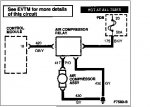
According to the kale mod schematics, you ground pin 18, the blue / yellow wire, to kick on the compressor. I didn't access the computer, there is a blue / yellow wire going to the relay. Normally, it has +12v. When the computer tries to kick on the compressor, it has +5v. The grey wire (the other small wire) going to the relay shows 0v. According to http://www.markviii.org/LOD2/suspension/fullsystemschematic.gif the grey wire is grounded and pin 18 is "input". According to http://www.markviii.org/LOD2/suspension/SolenoidSchematic6.gif you need to ground pin 18 to kick on the compressor (and I know this to be true from doing the kale mod on other cars). That doesn't seem to agree.

When I ground the DB/Y wire at the compressor relay, nothing happens. When I do that with the ignition on, it immediately says check air ride.

I tried swapping out the relay, didn't fix the problem.

I don't know WTF to do next.

I have a spare computer, I can try that, but i'm not too confident. I found a similar post from ponyfreak from 2003 with the same problem but no fix. He swapped the computer with no improvement.

Is there supposed to be +12v to the grey wire? That's the only thing I can think of.
 
The grey wire from the relay is ground.

Grounding pin 18 should cause the compressor to run with the key on.
 
Why am I seeing +12v at the DB/Y wire going into the compressor relay then?

I don't understand this relay. When the compressor is supposed to be off, you have 12v across the low current side. When the compressor is supposed to be on, you have 5v. WTF.
 
what's the input on the relay supposed to be? Anyone know how that thing works inside?

I suppose the next step is swapping the computer and seeing what happens.
 
It was the damn relay. The spare I had was bad too. The one from the abs fixed it. Time to buy a new one for the abs.

Unless... Anyone with coils have one to give away or sell cheap?

Btw... I apparently don't understand how these relays work. Good thing I'm not an ee. Oh wait... The ee who sits next to me didn't know either
 
Last edited:
I'm not sure of the inner workings, but from the EVTM the 4 connections are as follows:

A: BK/Y +12Volts from Engine compartment fuse box - 50A fuse (Air Comp)

B: P/O +V to compressor motor

C: GY 0Volts (Ground) to Splice S101

D: DB/Y "Compressor Relay Control" from pin 18 of Air Suspension/EVO Module

What is interesting, pin 18 shows to be internally switched to ground inline with an internal resistor. It is likely a current limiting resistor?

One diagnostic test is to connect a voltmeter between pin 18 and pin 32 - it should read battery voltage with the air suspension switch on and the black and gray connectors disconnected at the control module. Pin 32 should have less than 1 ohm resistance to battery ground with the air suspension switch on and the black and gray connectors disconnected at the control module.
 
Dammit!

It stopped kicking on again. Most likely, the compressor is drawing too much current and toasting the relay.

So I need to get off my wallet and come up with 2 relays and a compressor.

Dammit!
 
I just stumbled upon this thread because my 95 MK8 has several problems after sitting for too long including the Air Suspension. I haven't started trying to troubleshoot yet and I have a few questions.
1) Do these electronic relays fail often?
2) Where is the suspension control module located? It's not that warm out so I don't want to spend too much time outside looking for it.
3) Are these solid state relays expensive?
4) Does anyone have a mechanical drawing for one?

The reason I am interested in the solid state relay is because if they are expensive the functionality can be duplicated for a very reasonable cost. High current power mosfets/trenchfets etc are cheap (a few dollars) and very high performance compared to 90's technology especially in a low voltage application like a car electrical system. On my 90 Mustang I installed a MK8 electric fan and was burning out traditional relays every few months. I solved the problem using a 100 amp power fet and never had a problem again.

As far as why they are switching between 5V and 12V they likely are using a P channel mosfet with the source connected to 12V. When the signal is at 12V the gate to source voltage is 12V-12V=0V and the fet is turned off. When they apply 5V the gate to source voltage is 12V-5V=7V (actually -7V gate voltage with respect to source) turning on the mosfet. If they are using a mechanical relay they are either swithing a transistor on and off with the control signal or the coil of the relay is connected to 12V not ground so you still get that same 7V bias voltage on the coil.
 
Yes, the relays are expensive and they do fail often.

I don't know much about them, except that they have 4 wires and when the trigger wire voltage goes low, they trigger.:D

As you can see in the photo that driller provided, a lot of the relay is just a heatsink.

If you could come up with a cheaper solution I'd be glad to test the prototype.:D
 
Interesting... I thought of using a suspension relay for a fan bypass relay. Instead I went with a huge charging type mechanical solenoid relay.

Now I'm left wondering if you couldn't use a mechanical relay for the suspension relay? :rolleyes:
 
The technology for power mosfets has come a long way since the 90's! The power mosfet that I used to control the fan cost about 3$ (mine was a free sample from Fairchild) and was spec'd at 8 milliohms (that's .008 ohms) turn on resistance. The one that I used measured 5 milliohms so at the 20 or so amps that the fan draws the power dissipated was around .2 watts. I mounted it on a nice sized heatsink and a friend of mine laughed when he saw the spec on the fet and commented what is the heatsink for; to absorb the heat from the engine compartment.

Do a google on Fairchild FDA8440 as an example. This device is 5 dollars in the Digikey catalog and can handle 100A. with a turn on resistance of around 2 milliohms. Depending on what the compressor draws for current a heatsink might not be required.
 
Problem is, the computer is looking for the stock relay. If something isn't right, it'll throw an error immediately and stop working. I don't know what specifically it's looking for, but I know if you unplug the relay you get an error immediately.

It's worth a try, though.
 
I bet that it wouldn't be too hard to characterize the solid state relay and design a simple circuit that would fool the computer if it is actually necessary to do so. Is the computer actually looking at the relay or is it looking for a change in ride height or something else to happen? It seems from what I have read that it takes several seconds for the error to show when the relay goes bad. Barring trying to trick the computer only two electronic components are necessary to replace whatever is inside the solid state relay (one P Channel MOSFET and one reversed bias diode for back emf). I wonder if a blown relay can actually be used to house the new electronics. The blown device would provide the necessary connector plus more than enough heatsink area to cool the device.
 
I opened up a bad relay, and I don't think you could use it as a housing. Maybe, though.

The computer is actually looking for something on that line. If the relay goes bad, it times out after 90 seconds, but if you actually unplug the relay, it throws an error code immediately.

Speaking of... I just blew out another damn relay yesterday. And that's with a new(er) compressor. I had 1 extra, so i'm functional again, but now i'm worried.

My plan is to convert the system to complete manual operation. Then if the relay goes again, I will just run heavy gauge wire to a higher capacity momentary switch so that I can manually switch the high current to the motor. Or I'll just get a typical mechanical relay to accomplish the same. If I'm controlling everything manually, the duty cycle should be low enough that a conventional relay shouldn't be an issue.
 
If I'm controlling everything manually, the duty cycle should be low enough that a conventional relay shouldn't be an issue.

I agree. You'll likely be looking for a remote starter type solenoid to handle the current. Should be easy enough to install and control manually with switches for each corner.
 
I just read through the early posts and something bothers me. You said "Normally, it has +12v. When the computer tries to kick on the compressor, it has +5v." Is +5V normal? I read somewhere else that in order to turn on the compressor to ground the signal going to the relay. If the relay normally needs 0V or close to it and it is seeing +5V the switching transistor will likely not be turned on fully (saturated). In that condition the transistor will dissipate much more power do to a larger voltage drop across it and will fail because it will overheat.

You should confirm that 5V is normal maybe the problem is the control module. You should measure the voltage drop across the relay.
 
The manual says ...

The air compressor is turned on by the control module through the solid state air compressor relay. The relay is controlled through Circuit 420 (DB/Y). When the compressor relay Circuit 420 (DB/Y) is at battery voltage, the compressor is off. When the control module senses, through the height sensors, that the compressor needs to run, it switches Circuit 420 (DB/Y) to less than five volts. The solid state circuitry inside the relay allows current to flow through Circuit 175 (BK/Y) and Circuit 417 (P/O) to the compressor.

NOTE:
The compressor relay is a solid state device and does not respond to established relay testing methods.

Diagnostic procedures say 2-4 volts at circuit 420 is normal feedback voltage from module to open circuit 420.

You can see all of the module inputs/outputs here.

To recap...

Circuit 175 (BK/Y) is +VDC from battery.
Circuit 417 (P/O) is +VDC to compressor.
Circuit 420 (DB/Y) is control voltage from module.
Circuit 430 (GY) is ground.

Schematic attached.
 

Attachments

  • compressor_relay.JPG
    compressor_relay.JPG
    30.8 KB · Views: 0
That's not the best way to wire it. It is always better for a solid state relay to sink current than it is to source current; however it is what it is. Does anyone know how much current the compressor is supposed to draw?

Did you measure the voltage that the compressor sees when it is running (or better yet the voltage from circuit 175 input to 417 output)? The power dissipated by the relay is directly proportional to the voltage across it for a given current. Another possibility is that you have an intermittent short circuit and the relay is the fuse; however you would think that Ford sized the fuse appropriately.
 
Back
Top