Replacing the front struts on
a First generation Mark is so easy, is should be
criminal allowing a dealer to do it for you. This is an
expanded version, with pictures, of the instructions
that Maples8 posted long ago. I installed second
generation struts.
Tools Needed:
-
Turn off the suspension
switch, located in the truck on driver's side.
-
Set parking brake and
chock one or both rear wheels.
-
Break the tension from all
lug bolts on the front wheels. You will need your
wheel lug key if you have wheel locks.
-
Lift the front of the car
with a floor jack positioned on the motor cross
member at the center. If you do not have a floor
jack, use the car's trunk jack and jack up each side
as shown in the owner's manual. The wheels MUST
clear the deck. Use a jack stand to support the car
on each side at the motor cross member. IT IS
EXTREMELY DANGEROUS TO ALLOW THE CAR'S WEIGHT TO BE
SUPPORTED ONLY WITH JACKS.
-
Remove the wheel lug nuts
the rest of the way.
-
Remove each front wheel
and position it under the car's frame, just behind
the front fender opening. If a jack stand gives way,
the weight of the car will fall on the tire, not on
your foot or leg. You might lose a tire, but you
will keep your foot.
-
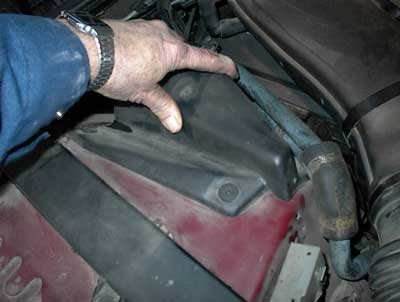
Pop the hood. Locate the
plastic covers. The following picture shows me
touching the plastic cover on the passenger's side.
There are two plastic "rivets" holding the front
part of this cover to the fender. The rear part of
the cover is held with plastic tension on a strut
bolt. The drivers side is partly hidden by an
electronics assembly. You might want to remove the
two 8mm sheet metal screws holding the electronics
assembly on. There may be a motor access connector
attached to the cover as well. If the screws turn in
the center of the plastic rivet but the screw does
not back out, you will have to help it. Insert the
small flat bladed screwdriver under the plastic
rivet and apply sideways pressure to the billows of
the rivet. Turn the screws with a Phillips
screwdriver while applying pressure to the center
and the screws will back out.
-
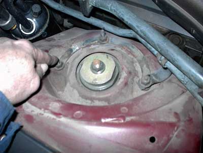
Remove the strut tower
nuts. The following picture shows me pointing at one
of these nuts. The passenger's side has FOUR nuts.
Note the nut holding the bracket at center right.
There is ANOTHER nut below that one. You can see the
edge of the second nut under the bracket.
-
Remove the metal washer as
shown in the following picture. After this task is
complete, you are done under the hood.
-
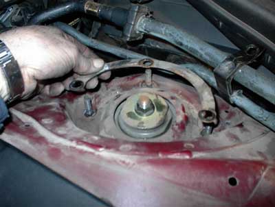
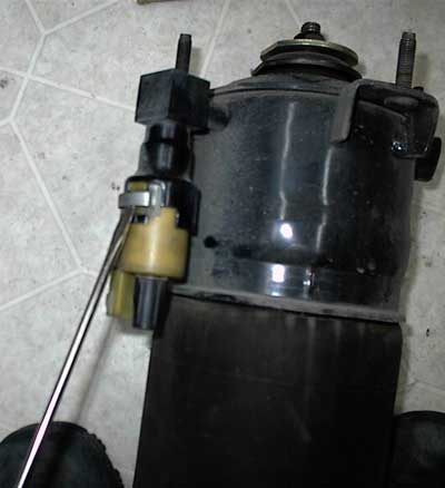
To gain access to the air
valve, you will need to reposition the height
sensor. The following picture shows me pointing to
this sensor. The sensor is held on with two ball
joints and spring clips. Rotate the sensor clockwise
as far as it will go and look at the upper ball
joint. There is a small rectangular metal piece
located there that is hiding the ball. Using a small
flat bladed screwdriver inserted between the joint
and the end of the spring, pull against the spring
tension while pulling the sensor toward the strut.
Once free of the ball joint, swing the sensor top
toward you and out of the way.
-
Again using the small flat
bladed screwdriver, pry gently on the ears that are
on both sides of the air valve while you wiggle the
connector and apply downward force. Once the ears
are moved away from the slight catch in the plastic
side of the valve body, the connector comes off
easily.
-
Air is supplied to the
valve using a single black plastic hose. There is a
bright orange collar at the top of the plastic hose.
This collar is an internal expansion collet, not
unlike what you would find holding the drill bit in
place on a Dremmel tool. The hose tip is flared. If
the hose if pulled on, as if air pressure is
applied, the flared end of the hole will expand the
collet and the two pieces can't go though the
smaller hole the collet is setting in. To remove the
hose, push UP on the collet (deeper into the valve),
while you pull down on the hose. This allows the
collet to receive the flare. It acts as a funnel and
the hose will slide out of the valve and collet. Now
keep pulling the hose down with a gentle wiggle
motion. The first time I tried it, both the hose and
the collet came out. The second time, the collet
remained inside the air valve and just the hose
slipped out.
-
Now squeeze the bag. If
you can squeeze the bag, you will not have to remove
the captured air. Go to step 17. If you can't
squeeze the bag, there is air in there and you will
NOT be able to remove the strut from the car. I
tried compressing a strut that was totally slammed
(but still had enough air in the bag to be "not
squeezable") with a hydraulic jack. I ended up
lifting the car off of the jack stand on that side.
So you need to either remove the valve or knife the
bag.
-
The pros, when replacing
the struts, use a LOCK BLADED knife and stab the
bag. They then twist the knife to allow the air to
escape around the knife blade. DO NOT ATTEMPT THIS
WITH A NON LOCKING POCKET KNIFE! The bag is very
tough and a non-locking blade may close on you when
you stab. You could cut your fingers off!
-
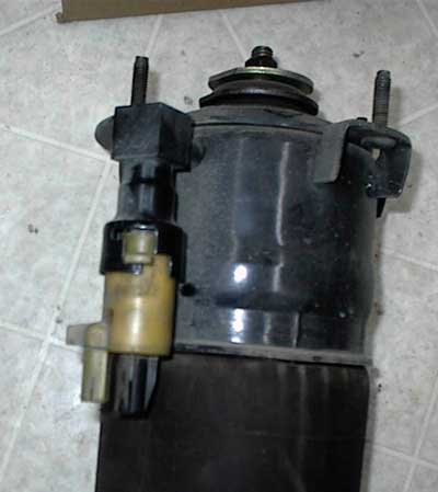
To remove the valve,
notice the picture below. The metal clip at the top
of the valve prevents the valve from rotating. Lift
up on the wide tab and rotate the spring clip around
toward the back of the valve. There is an identical
tab in an identical slot on the back side of the
valve.
-
Once the spring clip is
out, you can turn the valve counterclockwise. Once
the plastic tab is free of the slot in the valve
cup, pull down the value to the next lower level as
shown in the picture below. This will allow the air
in the bag to escape. You can now squeeze the bag.
You do not have to remove the valve completely. If
you do want to remove the valve completely, turn it
again counterclockwise and pull it down after the
plastic tab is free of the second slot in the valve
cup.
-
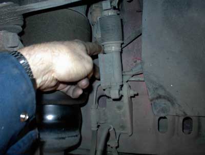
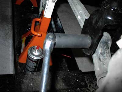
Now you are ready to
remove the lower shock absorber (strut) nut. Using a
21mm socket and a breaker bar, grunt down on the
nut. The bolt head on the other side of the strut
has a metal ear that prevents the bolt from turning.
According to the service manual, this nut was put on
with a torque of between 199 to 243 ft-lb! The
picture below shows us getting down and dirty on the
nut.
-
Once the nut is off, tread
it back on the bolt and tap it with a hammer to push
the bolt out. Leaving the nut on protects the
threads of the bolt. You might find it helpful to
wiggle the strut up and down while you are tapping
on the nut with a hammer. Also, the bolt head and
metal ear must clear steering parts. I was able to
turn the steering wheel one way or the other,
depending on the side I was working on, to allow the
bolt to clear the parts as I hammered the bolt out.
Use a long punch to tap the bolt on through the
strut mount, if needed.
-
With no air pressure to
fight you, it's an easy task to "compress" the strut
and lift it off of the lower mount.
-
Mount the new strut in the
reverse order. My struts were "pre-charged" with
air. I had to make the bag squeezable by loosening
the valve. Once installed and the lower bolt is in,
you can reconnect the valve and attach the spring
clip.
-
Ford suggests you tighten
the lower nut between 199 to 243 ft-lbs. That's a
lot. I figured 100 to 150 ft-lbs would be fine.
-
Connect the air hose to
the valve next. Just push it up into the collet. You
may hear the collet click as it grabs the flared
hose end.
-
Now check to see if the
valve is properly held in place with the spring
clip. Then slide the electrical connection into
place.
-
Under the hood, install
the ring washer and three mounting nuts. Tighten the
nuts between 17.2 to 23.4 ft-lbs. Don't forget the
fourth nut on the passenger's side that holds the
bracket. Put the electronics back in place on the
driver's side.
-
Install the plastic covers
over the shock tower.
-
Before removing the jack
stands, I lowered the car to the minimum jack stand
height and turned on the air suspension switch in
the trunk. This allowed the compressor to pump up
the new struts without the full weight of the car on
them. I then shut every thing down and removed the
jack stands completely. The car still looked
"slammed" to me. Some members suggest manually
turning on the compressor to air the struts before
you bring the car off of the jack stands. Care must
be taken here in that you don't "forget" you turned
on the compressor and over-inflate the bags.
-
When my warranty company
did HOTLNC's front struts (1200 bucks!) last year,
they wanted to check wheels alignment. Of course,
that wasn't covered. I questioned the sanity of
checking the alignment since no alignment critical
part was replaced. I was told it was "policy." Fine
- I told them to go ahead and paid the extra 60
bucks with a fair amount of grumbling. So fine.
Maybe you would like to have the alignment checked?
-
You are done.