AC Tribulations

driller

El Presidente
Staff member
With spring in the air, it was time to pull out the toys and have some fun. With plans of taking the Opal Opalescent '96 to Carlisle and then on the Hot Rod Power Tour, it was imperative to try to get the AC to work. It last worked probably sometime late 2019 as it has been literally sitting around since the start of the pandemic. I've moved it a time or two to make room in the garage for other projects but for the most part it hasn't really been used. I do remember feeling somewhat despondent when I moved it one time and noticed the AC wasn't working but it wasn't on the front burner, so we simply shrugged it off as needing to be recharged when the time came.

No problem except the one shop I had trusted before to work on my vehicles had closed their doors last year so I was forced to try to find another shop I would put trust in to work on my fleet. Not an easy task, especially when you have heavily modified vehicles such as mine. So I embarked on the journey as a "let's see what these guys can do" thing. So I called and setup an appointment for a state inspection and AC service.

After an hour or so of the car being in the service bay getting worked on, the service tech informed me the car passed inspection but they were trying to figure out why the compressor wouldn't run. OK, I thought, something simple like the cycling switch. They'll figure it out. :unsure:

Well, not so lucky. After another hour or so they determined the VCRM was the culprit. Not a problem, I'm sure I have a spare I informed them. I would see if I could find time to work on replacing it or worst case I would return next week with the spare for them to change out. As it turned out, I managed some time over a couple evenings. For the life of me, I couldn't manage to access it from the top or underneath, so I bit the bullet and pulled the front bumper cover to be able to access it. I couldn't tell any difference after the removal and replacement but I made an appointment to return to the shop and have them finish the work.

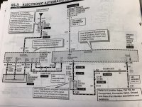
So now in the second session, the service tech asked me to come take a look after an hour or so. He had diagnosed a wiring problem where there was no continuity between the VCRM and the AC clutch. I referred to the EVTM which I brought along and compared it to the schematic he was working from. There was some discrepancies but regardless we still could not establish continuity.

The day was fast ending, so the decision was made to put everything back together and I would try to further troubleshoot the issue or if I couldn't find the time, bring it back to them and allow their tech to continue the search.

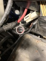
The oddity to me was the path the wiring takes from the VCRM to the AC clutch. The wire routing goes from the VCRM to the drivers corner of the firewall where it jumps back to the engine harness and routes to the AC clutch. So the troubleshooting route will be to ascertain the specific wires at the harness connections and attempt to determine whether the fault lies between the VCRM and the harness connection(s) or the AC clutch and the harness connections. Should be fun. :p

My thinking is to start at the AC clutch harness pigtail. Knowing the issues with different Ford harness pigtails, such as the alternator, crank sensor, cam sensor, etc..., it seems logical to me the AC clutch harness pigtail wouldn't be any better. Meanwhile, I'm thinking of a backup plan, like cutting and splicing a pair of wires from the VCRM to the AC clutch?

To be continued... :giggle:
 
Just out of curiosity did they verify there is freon in the system.I,ve worked on ac systems that had an ecm problem and I ran 12 volts right to the compressor for verification.
 
The initial AC check not surprisingly showed literally no charge. They evacuated the system and held a vacuum for 20 minutes or so to verify no apparent leakage. They then charged the system with refrigerant and tried to engage the AC. They jumped the cycling switch to no avail and then attempted to diagnose why the AC clutch was not getting power. They did at some point apply power directly to the clutch to verify it functioned. With the VCRM replaced and everything else presumably in working order, that's when they started diagnosing continuity in the wiring.

As of today, I haven't had any time to look at the wiring. I was sidetracked when the DS power window suddenly decided it would not go up. I checked the switch and it is working, so now I have to pull the DS door panel for further troubleshooting. :poop:
 
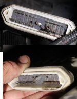
My 98 seems to have random wiring problems like that. Often I suspect the splices in the harness but they are usually so deep into harness I don't want to take apart the whole harness to get at one wire. The wiring diagrams show where the splices are in the back of the book but it's not worth opening all the wires up and risking other problems. I just run a jumper wire of the suspected wire, properly sized and soldered in, routed the easiest way. This is a great diagnostic tool too but if it works, I clean it up and call it a day. Also, does the connector look ok? Remember I fried my VRCM connector last year.connector before after.JPG
 
Also a good smack on the door pad with the window switch in the up position usually helps my occasionally stuck window motor. (edited mine usually get stuck in the up position, if yours is stuck down, hold the switch in the up position when you smack it).
 
Last edited:
I just run a jumper wire of the suspected wire, properly sized and soldered in, routed the easiest way. This is a great diagnostic tool too but if it works, I clean it up and call it a day. Also, does the connector look ok? Remember I fried my VRCM connector last year.
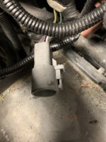
Yes, the connector looks pristine. I remember what happened to you last year at the Lincoln Homecoming. When I couldn't get to the VCRM, I was going to call you and ask how you were able to get to the VCRM without pulling the bumper cover.

Once I get into it, my backup plan is exactly what you describe, running a separate wire spliced in from the VCRM direct to the AC clutch. (It won't be going to the firewall, LOL)

First, I want to get a new AC clutch connector pigtail and temporarily use it to supply fused voltage and ground to the AC clutch to verify the clutch and compressor functions. Then I will go ahead and splice the new pigtail in place of the old one. In my experience that harness connection is the most suspect (because that's what Fords typically do).

Failing that, my plan is to identify the wires at the harness connections up next to the firewall and try to isolate which 'leg' in the circuit is open, starting from the AC clutch side. I certainly don't plan to track the wires along the entire course of the harness(es), especially the VCRM side.
 
Yes, the VCRM is horrible to get to. I remember using 1/4" with U joint and still taking too long and cutting my hand up,
 
Also a good smack on the door pad with the window switch in the up position usually helps my occasionally stuck window motor. (edited mine usually get stuck in the up position, if yours is stuck down, hold the switch in the up position when you smack it).
I had smacked it several times with the palm of my hand and later my fist with no luck.

The second blow with a dead blow hammer snapped it back to life! (y)
 
I had smacked it several times with the palm of my hand and later my fist with no luck.

The second blow with a dead blow hammer snapped it back to life! (y)
Glad to hear it! That usually works with a stuck motor from sitting too long. I see them try to do that on Roadkill all the time with starters and a wiper motor, but it doesn't work for them because they don't apply power while smacking it.
 
Found a little bit of time to work on it today.

I verified the AC clutch functioned with voltage applied. I then tried to establish continuity from the AC clutch connector to the engine harness connection at the firewall. Nothing, nada, zilch. On either of the two wires, voltage or ground, to any pin on the connector. :mad:

I verified the ground circuit at the engine harness connector but could not confirm the AC clutch voltage circuit on the engine side of the harness connection. The wire color on the harness connection did not match those shown in the EVTM.
 
.
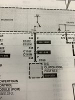
Strange, my 94 manual shows the P wire goes to 2 connectors from the VCRM, to the clutch coil, is that the same on the 96? I know some things are a lot is different between the 2 years.
 
.
Strange, my 94 manual shows the P wire goes to 2 connectors from the VCRM, to the clutch coil, is that the same on the 96? I know some things are a lot is different between the 2 years.
Yep, same here. Circuit 348, P(purple) wire from pin 18 on the VCRM through connectors C121 and C118 to the AC clutch coil.

tempImagenOwt02.jpg

I'm frustrated and 95% sure this isn't what is in the car. I cut the old connector off the harness at the AC clutch in preparation to splice in a new one. I tested the old one and did have some continuity issues with a wiggle test where the wires go into the connector. So that made me a little upbeat thinking the new pigtail would cure the problem. While I had the wiring exposed at the AC clutch, I tried a continuity check from the purple and black (not GY/W) as the EVTM calls out but still could not find the circuit in the connector by the DS firewall. :mad:

tempImagebgtr9g.jpg

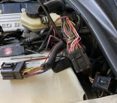
Here are the harness connections for the engine harness...

tempImage1UjxF4.jpg

Funny how I just realized it's a lot easier viewing the wire colors in a picture than in person. I can zoom in and see them a lot more clearly. :D
 
Yes, I zoom in on photos all the time. Did you verify the wire colors at your VCRM connector pin 18 (P) and pin 1 (BK, it looks like your GY/W turns into BK at your connector C121). My P and GY/W wires are on my pins 14 and 13 and my GY/W does not change to BK like yours does.

CUTIMG_5960.jpg
 
After much frustration, I concluded that circuits 348(P) and 321(GY/W or B) were NOT at the firewall connectors per the EVTM! OK, I thought to myself, if they were not there, where were they and how do they route to the VCRM? :unsure:

As it turns out, they are routed similar to the Gen2(at least the '97). I happen to have a '97 EVTM and searched the same circuit(s) and noted the AC clutch coil circuit did not pass through the firewall connector(s) but routed around the engine along with the fuel injector wiring harness and to another connector(C116) under the fusebox in the engine compartment. It didn't take long to track the harness and locate a split sleeve tubing taking off from the fuel injector harness at the DS front of the engine. Sure enough, upon opening the harness covering there were a purple and black pair of wires! It appears they disappear under the engine compartment fusebox and likely enter the body harness enroute to the VCRM. (The C116 connector simply allows a path from the engine harness to the body harness.)

Knowing that, the plan now is to splice in the new AC clutch coil harness pigtail and put everything back in place. If it still does not work, we will route a new pair of wires direct from the VCRM harness to the AC clutch coil. 🥲
 
Figured it was time for an update.

Here was the C116 connector I found with the purple and black wires from the AC clutch...
tempImage1tepvV.jpg

tempImageIcTNAa.jpg

Unfortunately I could not find any mating connector in the vicinity to plug it into. :( So I searched online to find the female connector to match and came up with a trailer plug kit for 80's-90's Rangers and F150s meant to plug into the tail lamp harness for a plug and play 4-wire trailer light plug. I scavenged the female connector from the kit with plans to use it for a quick connection for a pair of wires to the VCRM.

After 4 hours this afternoon at the shop, we were no further along than when we started. After routing from the connector and splicing the appropriate wires at the VCRM there was still no AC clutch engagement. After swapping in 3 other VCRMs, still nothing! They checked continuity, grounds and still no luck. We could 'see' battery voltage but it would not carry any load (not even a test lamp). Typical of a solid state relay as what would be in the VCRM. Ground circuit to the VCRM was good as well as battery feed.

The only remaining course is to investigate the data network which communicates between the PCM and the different modules. It is apparent the VCRM is simply not receiving the command signal(whatever that may be) from the PCM to engage the AC clutch. Which is odd since the VCRM is controlling the fan and fuel pump as they are both functioning as they should. Just not so much with the AC clutch. Also, the EATC functions as it should and it passed the self function test too, so we don't suspect it is bad.

I can't recall when I last have been so stumped. :cautious:
 
Further update...

After some (well, OK, a LOT of) thought, I decided to look in the Powertrain Control Emissions Diagnosis Service Manual for some insight on the communication network between the PCM and various modules. Long story short, I stumbled upon a rather detailed diagnostic flow chart for troubleshooting the AC clutch function of the VCRM specific to the Mark VIII. Apparently you can use a diagnostic scanner(such as the Ford NGS tester) to access certain PIDs(Parameter Identification Data) in the PCM to ascertain correct EEC-V functionality.

I believe I may have discovered Pandora's Box... :p

After some quick review, I have some homework to do to weave my way through the diagnostic procedures, but I think if one of my handheld tuners or even my Innova OBD2 Scanner can access the PIDs in question, I just might be able to figure out specifically what is not functioning as it should. :unsure:

To be continued...
 
Last edited:
Sounds encouraging JP. Have you tried wiring the clutch directly to the battery to see if the AC works? Maybe if you can't find the problem, a separate switch and relay would be a temporary work around to have the AC working?
 
Have you tried wiring the clutch directly to the battery to see if the AC works? Maybe if you can't find the problem, a separate switch and relay would be a temporary work around to have the AC working?
Yes, the first trip to the shop they said they checked the AC clutch by putting battery power to it. I also tested it that way when I put in the new harness pigtail, just to be sure myself. And this last visit, somewhere after the 2nd trial VCRM, the AC clutch was again verified to be functional by jumping battery voltage to it.

Indeed I have thought of doing it 'old school' via a switch. After all, I tease my wife all the time that she only needs a red button and a blue button for the vehicle HVAC because she either has it full heat or max AC with the blower on max all the time. But seriously, you can in fact dumb down the system with what they call a "trinary switch". The switch is simply a three way pressure switch (in place of either the cycling switch or the pressure transducer) which controls both the low set point and the high set point for the AC compressor as well as activating an electric fan via a relay when the AC is on to draw air across the condenser. Pretty sure I could do that as a worst case while using the EATC to control air temp and blower functions. I already have a Dakota Digital programmable fan control which has an AC trigger which could serve as thermostatic fan controller for engine cooling.

If I do something like that, either temporary or permanent, I would only need a heavy duty relay for the fan. I wonder how the solid State relay Lincoln uses for the air suspension and ABS would work? Pretty sure I have a couple spares around... :unsure:
 
Here's my homework:

  • The AC cycling switch opens/closes according to system pressure to keep evaporator from freezing over.
  • The AC cycling switch circuit feeds an input to the EATC.
  • The EATC sends a signal via the SCP datalink circuit to the PCM.
  • A pressure transducer sends a control signal from the AC condenser to interpret hi/lo pressure limits for the AC system.
  • The PCM then sends a signal via the SCP datalink circuit to the VCRM if allowed with the AC system pressure.
  • The VCRM then sends sends battery voltage to the AC clutch circuit.
The PIDs to datalog this process are the ACC (AC Clutch Command) and the ACP (AC Pressure).

  • ACC PID returns 1 = AC on, 0 = AC off.
  • ACP PID returns AC Pressure in PSI.
  • The SCT LiveLink software I use can datalog both ACC and ACP PIDs.
  • The Innova 3160d OBD2 scanner I use can also datalog PIDs (though I need to confirm once connected to the car).
With all this, one should be able to determine if the EATC is getting the signal from the AC Cycling switch which subsequently triggers the AC Clutch Command along with the system pressure according to the ACP PID. Hopefully sometime this weekend we can devote some time to diagnose the problem and plan a course of action. I've already ordered a trinary switch just in case but I still need to source a suitable relay if I go that route.

Edit... neither the handheld SCT X4 tuner nor the Innova OBD2 scanner will access the ACC or ACP PIDs on their own. That means I will have to break out the big guns and hook up the laptop and utilize SCT's LiveLink software. :cautious:
 
Last edited:
Back
Top