Steering Column Loose

budpytko

Registered
Driving today and the steering column made a "THUNK" and now has slop in the column. The motors for the up/down and in/out still work okay, but every time a turn a corner the column itself moves around from left-right and a inch or so. I'm sure it's probably the ball bearings inside, but my question is, does the whole column have to come out of the car to repair it?

Does anyone know if Lincoln has repair kits for this problem? And I remember a step by step that we used to have in here, but I guess it got swallowed up when we upgraded the software. Did a search and got the message to go here (http://www.lincolnsclub.org/forum/dc...&topic_id=4827) but that place doesn't exist anymore.

Anyone know where it went or how we can retrieve it? Last thing, if anyone has done this repair, how long a job was it?

Thanks for any help. Jamie, you got any parts in case Lincoln can't help me?
 
If you can find all of the balls, you wont need any more parts. Might check with the FLM dealer to see if the TSB has been done on your car. It involves the addition of installing travel limiting cables.
 
:) Gotta love All Data...

99B08 05/01/1999 Campaign - Steering Column Restraint Installation

I even have the instructions for fixing it too.....if they don't do it at the dealer.
 
Last edited:
Jesse, I'm a-gonna need those instructions....A TSB isn't warranty! And I'm WAY out of warranty anyway! e-mail 'em to me if you wish.
 
When i messed with my columb i did it in the car cuase i couldn't get the bolt to come out of the knuckle. And eventually stripped it, dam lok tite. Just take out the plastic knee panel, the black panel behind it, remove 4-5 elec connections on the columb (on the bottom of it), Take out the 4 bolts holding the columb to the dash. Now it should be resting on the floor.
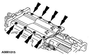
Use t-30 torx bit to remove the 8 bits on the top. When you open it up you'll see if the bearings(2) in the plastic slider are intact. There is one on the top and bottom of the columb. The tops alot easier.
I mangaged to mis alighn the bottom on accident but was able to stuff it back in there while moving the wheel.

Also, When i tried mounting the columb back up the bolt holes didn't match up and had me stumped. I later found out that the steering shaft got moved into the engine comp 1.5"s, pulled it out and lined it back up.
 
Thanks Brad.... did you remove the front seat to get extra room to work or anything else?

Did you leave the Air bag intact and in the steering wheel?

Sure appreciate the info.
 
Yea i left the airbag inplace. Though as you know i'd disconnect the battery first :) The seat stayed in the car and i had enough room to work comfortly. Check this link out for some help.

http://www.lincolnsonline.com/tech/00118.html


Kinda sucks for me though, I had to open it up to manually adjust the controls so that the steering wheel would come out more and as soon as i turned on the car it went all the way back in. Next time i feel like ripping it out again i'm going to disconnect that dam telescopic motor. My in works, and the tilt up/down but no out. grrr....
 
Weird...exactly same thing with mine...found the upper ball cage and tracks lying in various places inside the housing. Lucky...all the bearing were still in the cage. As I didn't have any pics of where/how the tracks went in I put 'em where I thought they'd go. One is long and one is shorter. When I got back together everything was good except the in/out function. Up/down was okay. Dropped it back down with all wiring intact and watched it...it looks like it trys to go even further IN than is allowed. The drive shaft actually bows a little. Push switch the other way (OUT) and it dun't do nuthin' !

As I want to drive it to NY Monday, I'm leaving it this way until I can get better instructions on how it goes back together (if I did it wrong) or if somehow I bunged up the electrical pot. But I don't see how.

The only other thing I did't like was that plastic (mine's black) piece that goes in the inside towards the passenger side of the column before the cover is bolted down. It doesn't seem to set flush in there...cover went on okay tho..

Jesse...I sure could use those drawing if you could send 'em. If too big to put on here, email 'em if my hotmail account will accept whatever size they are. If it don't come thru, I can give you a better address via email.
 
Apparently this is the TSB for installing new cable restraints........

AFFECTED VEHICLES:
1997-1998 MARK VIII

SERVICE PART NUMBER F7LZ-3L595-AA

SERVICE PROCEDURE

1. Telescope steering column to fully extended position, tilt to the mid-tilt position.

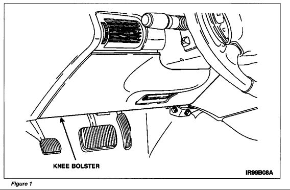
2. Remove the knee bolster. See Figure 1
Column1.gif


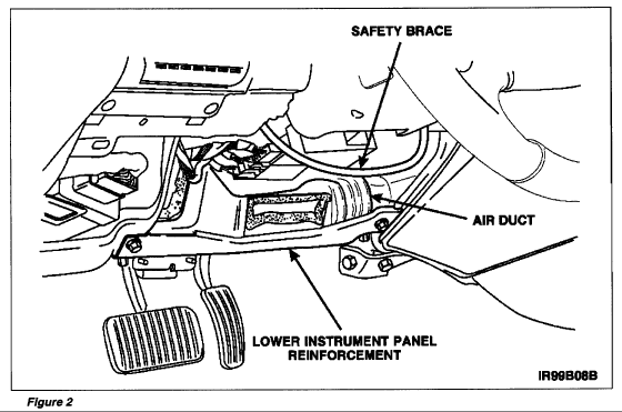
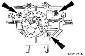
3. Remove the lower instrument panel reinforcement. See to Figure 2.
Column2.gif


4. Remove the air duct. See to Figure 2.

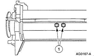
5. Remove the steering column safety brace. See Figure 2. The safety brace is held in place by the two (2) front steering column retaining stud/nuts.

CAUTION Do not remove rear steering column nuts as damage to the steering column could occur.

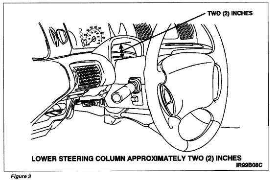
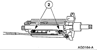
6. Support steering column, then loosen the two (2) rear steering column nuts enough to lower the steering column approximately 2 inches. See figure 3.
Column3.gif


7. Remove the upper and lower steering column shrouds.

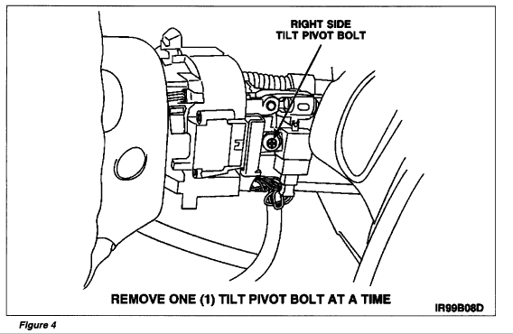
WARNING DO NOT REMOVE RIGHT AND LEFT TILT PIVOT BOLTS AT THE SAME TIME. THE STEERING COLUMN TILT SPRING COULD EJECT FROM THE STEERING COLUMN, RESULTING IN PERSONAL INJURY.

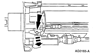
8. Remove and discard the right side tilt pivot bolt. See Figure 4.
Column4.gif


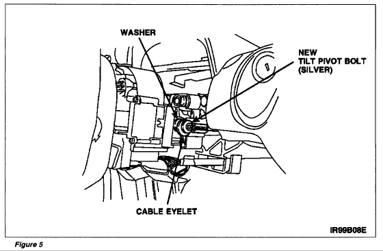
9. Install washer, right retaining cable (eyelet end), and NEW SILVER TILT PIVOT BOLT into right side pivot bolt bore. Make sure eyelet is indexed to the 3:00 o'clock position. Tighten pivot bolt to 24 Nm (18 lb-ft). See Figure 5.

WARNING DO NOT REMOVE RIGHT AND LEFT TILT PIVOT BOLTS AT THE SAME TIME. THE STEERING COLUMN TILT SPRING COULD EJECT FROM THE STEERING COLUMN, RESULT IN PERSONAL INJURY.
Column5.gif


10. Remove and discard the left side tilt pivot bolt.

11. Install washer, left retaining cable (eyelet end), and NEW SILVER TILT PIVOT BOLT into left side pivot bolt bore. Make sure eyelet is indexed to the 9:00 o'clock position. Tighten pivot bolt to 24 Nm (18 lb-ft).

12. Install both upper and lower steering column shrouds.

13. Raise steering column to installed position, then tighten the two (2) rear steering column retaining nuts. Do not final tighten nuts at this time.

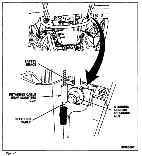
14. Position rear mounting clips of both retaining cables over the steering column front retaining studs, then install the safety brace over the retaining cables. Install the front steering column retaining nuts. See Figure 6.
Column6.gif


15. Tighten all four (4) steering column retaining nuts to 34-46 Nm (24-34 lb-ft).

16. Install the air duct.

17. Install the lower instrument panel reinforcement. Tighten retaining bolts to 13-17 Nm (10-12 lb-ft).

18. Install the knee bolster.

19. Check operation of steering column.


Here is the Disassembly Procedure of the column......

Remove the steering column assembly.
Remove the steering wheel and the multi-function switch.

Remove the shock absorber electronic steering sensor.
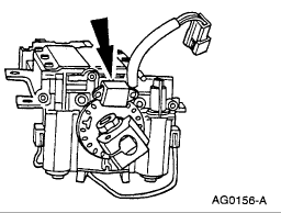
Column7.gif


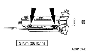
Remove the tilt and telescope motors.
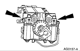
Column8.gif


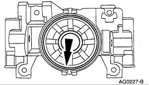
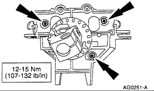
Remove the housing cover.
Column9.gif


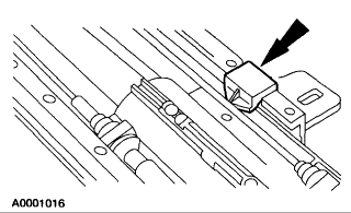
Remove the potentiometer link.
Column10.gif


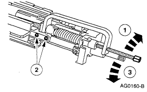
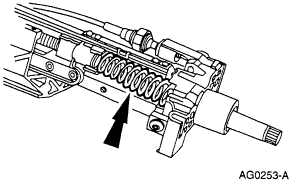
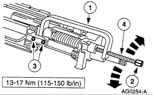
Remove the tilt spring.
Install the Tilt Spring Compressor (1) finger-tight.
Remove the telescoping actuator retaining bolts (2).
Slowly turn the tilt spring compressor bolt counterclockwise (3) to release the spring tension.

Remove the tilt spring compressor and the tilt spring.
Column11.gif


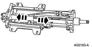
Separate the front and rear halves of the steering column shaft. NOTE: Index mark the steering shaft tube to show the location of the steering shaft flat.
Column12.gif


Remove the potentiometer.
Turn the housing upside down.
Remove the retaining screws.
Remove the potentiometer.
Column13.gif


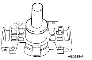
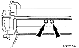
Remove the telescope actuator.
Remove the retaining nuts.
Remove the telescope actuator.
Column14.gif


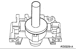
Separate the front steering shaft assembly from the support housing.
Column15.gif


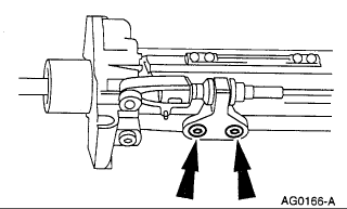
Remove the tilt actuator pivot pin.
Column16.gif


Remove the tilt actuator.
Remove the retaining screws.
Remove the tilt actuator.
Column17.gif


Remove the tilt pivot bolts.
Column18.gif


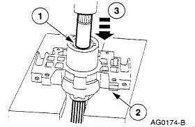
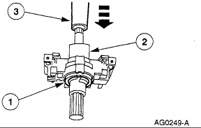
Press out the rear steering shaft.
Remove the retaining ring (1).
Position the bearing housing on the press bed (2).
Press (3) out the steering shaft.
Column19.gif


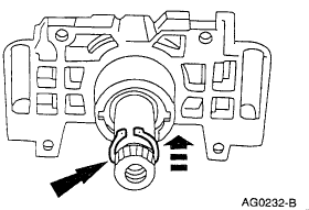
Remove the steering column rear small bearing.
Remove the small bearing retaining ring (1).
Using a suitable brass drift, drive out the small bearing.
Column20.gif


Remove the steering column rear large bearing.
Using a suitable brass drift, drive out the large bearing.
Column21.gif
 
Steering Column Assembly.............Reverse disassembly procedure. hah just kidding! :)

Install the steering column rear small bearing, pressing only on the outside race.
Column22.gif


Install the steering column rear small bearing retaining ring.
Column23.gif


Install the steering column rear large bearing, pressing only on the outside race.
Column24.gif


Press the rear bearings and housing onto the steering column shaft.
Support the large bearing inner race on a press bed with a suitable sleeve (1).
Place the bearing housing (2) over the steering column shaft.
Place a suitable sleeve (3) over the short end of the steering column shaft that will seat on the small bearing inner race.
Press the bearings and housing onto the shaft.
Column25.gif


Install the steering column shaft retaining ring.
Column26.gif


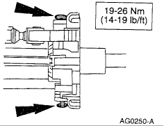
Attach the bearing housing to the center housing. Install the pivot bolts.
Column27.gif


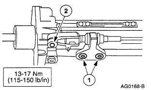
Install the tilt actuator.
Install the retaining bolts (1).
Drive the pivot pin (2) into place.
Column28.gif


Install the potentiometer.
Column29.gif


Attach the front steering shaft end plate to the support housing, install the retaining bolts.
Column30.gif


Install the telescope actuator.
Position the actuator inside the support housing.
Install the retaining nuts.
Column31.gif


Connect the front and rear steering column shafts.
Align the index mark on the front shaft with the flat on the spline of the rear shaft.
Slide the rear shaft into the front shaft.


Install the tilt spring.
Column32.gif


Install the telescope actuator retaining bolts.
Install the tilt spring compressor (1).
Turn the tilt spring compressor bolt (2) clockwise until the bolt holes for the telescope actuator align.
Install the telescope actuator retaining bolts (3).
Remove the tilt spring compressor (1).
Column33.gif


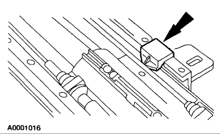
Install the telescope potentiometer link.
Column34.gif


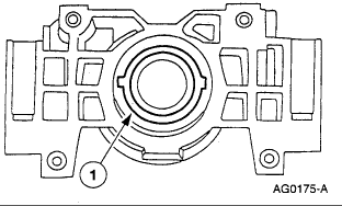
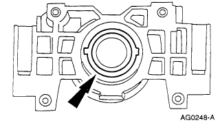
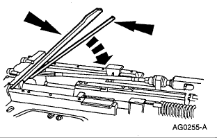
Position the ball bearing track and housing cover into place.
Column35.gif


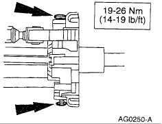
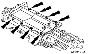
Install housing cover retaining bolts.
Column36.gif
 
Thanks Jesse, but I already had THAT..or most of it anyway. What I really wanted was the info in the original thread that shwed the insides and the bearings, etc. It was this link: http://www.lincolnsclub.org/forum/dc...&topic_id=4827 - but that's a dead link now. Guess when we "upgraded" the software here on the site, it lost the original posts in a lot of the How To: things we used to have.
 
Sorry....I posted everything I could find. No "exploded" pics of the column that showed any detail.
 
Oh well...just got back from driving it to upstate NY and back....about 1000 miles.... and I didn't have a problem with it the way it is...I may just let it go...It tilts up and down, just doesn't go in/out. I used the seat adjustment for that reach! Worked well...I'm gonna contact JP and see if he can't find this old link. If he can, I'll drop it down again and see if I can fix it.
 
Back
Top