97 Aftermarket HU install w/JBL...

TheMarksman

New member
Hello all. I have searched more than several posts here about JBL systems, aftermarket installs & all. There is even a diagram of the pin-outs there ---------> http://www.lincolnsofdistinction.org/vbulletin/showthread.php?p=166888#post166888

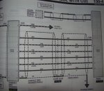
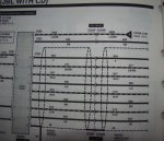
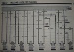
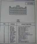
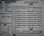
My question is, my connector is a 16 pin with only 10 pins used. The 8 pin connector I understand, But I have 2 extra wires coming out of my connector as seen here ----v http://i634.photobucket.com/albums/uu62/SVTurboCoupe/1360416329.png

What I did was cut the connector from the harness and trying to straight wire it into the Scosche FA13A converter. I just don't know where that black wire & that green w/ blk stripe wire goes. As of now, I have NO sound...
Thanks.
 

Neil

New member
It looks like those linked diagrams are for a 93. You should find a set of 97 diagrams. There are different ones for Premium Sound, JBL and JBL w/CD changer.
 

Neil

New member
I have a 96-99 Ford Manual on CD. It does not show a single CD radio diagram and the other diagrams don't show a yellow wire in the speaker output wires like you show ( in the JBL system they are actually outputs to the amp). I wish I could help more but I can't find a diagram that matches all the colors on your cut off connector.
 

Neil

New member
Thank you for posting those Bill. Those are the ones I was looking at but I thought wire 859 was a V (violet) instead of a Y (yellow). I guess I need glasses! Unfortunately for The Marksman those two wires wouldn't cause a "no sound" condition.
 

TheMarksman

New member
THANK YOU billcu!!!

However, I haev decided to straight wire the speakers for ease of doing. I've taken the amp out. I was trying to follow the color codes for the speaker wire(s) to properly connect them instead of running new wire, but it seems inevitable. For instance, I know the color codes for the speaker-wire running FROM the radio to the amp, but the colors are completely different running FROM the amp to the various speakers....THAT'S where I am now getting lost...
 

TheMarksman

New member
THANK YOU once again billcu! Now, from the diagram above, it looks like the from AND rear speakers are bridged into one another, correct? And also, what is a "shield"?
 

izackary

Nomad
Damn, Bill! I should have PM'ed you when I was investigating the possibility of fabricating a home-made Aux-In adapter!! I was looking all over the interwebs for those exact diagrams. I REALLY need to get factory service manuals... :rolleyes:
 

izackary

Nomad
THANK YOU once again billcu! Now, from the diagram above, it looks like the from AND rear speakers are bridged into one another, correct? And also, what is a "shield"?
Most likely a braided shield grounding sensitive cables (ie: line-level from the CD Changer) from outside interference. It is often grounded on one end of the connection.
 

chris2523

New member
Most likely a braided shield grounding sensitive cables (ie: line-level from the CD Changer) from outside interference. It is often grounded on one end of the connection.
indeed. as i recall, its like a foil wrap around the wires, inside of the outer insulation.
 
Top