OBDII Tuning

racecougar

New member
Yep, a leak at the collector can certainly skew the O2 readings, even though the sensor is "ahead" of the leak. That said, it's common to see a little variation in the STFT's between banks, and the difference will typically remain constant.
 

driller

El Presidente
Therein lies the rub as it does not seem to be constant.

Further testing appears to show once the car is above 2500 rpms or so, the two values almost snap back to where I think they should be? I need to look at the logs more and I need to log some other car and get some idea of what supposedly proper STFT data should look like.

Last night I put the car on the lift and did indeed note a small leak at the PS collector flange. But even worse was a very small leak at the collector itself upstream of the O2 sensor! :eek:

Regardless, the plan remains the same. It could be the collector leak on the RH side will skew the O2 results at idle or low load but be plenty fine in the big picture. New O2 sensors are on order just because I can progress through this eliminating them as suspect. I have new collector flange gaskets and may try to JB Weld the collector just for testing purposes.
 

markup97

Lost in Translation
Sounds like a plan, JP. I think you will find the O2 sensors will come into line when you fix those two leaks. It doesn't take much at idle. The exhaust pulse speeds up as rpm increases, making reversion less of an issue once rpm climbs. If reversion is reduced, so too will the skewed natures of the O2. Fresh air can't make it in and back up to the O2 if it is being beat back out by 10 pulses per second! (figure used just for reference)
 

driller

El Presidente
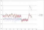
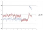
Here is a chart showing just the STFT values. At first is a period of idle while waiting for temp to get up around 170*, then a few seconds of 1500 rpms, then 2500 rpms followed by returning to idle.
STFT01.jpg

Note how the values "snap" to what appears they should be in the 2500 rpm range between 100 seconds and 135 seconds. Also note the big difference in the early idle values and the ending idle values.

It would be interesting to do a slow rpm 'sweep' (idle-3,500-idle) and see how the STFT's react. I know when I did so in Open Loop, the MAF tuning was remarkably steady with a Lambda value of 0.99-1.01.

If I average the values in the 2500 rpm section, the average Bank 1 STFT = 0.99 while the average of the Bank 2 STFT = 0.98 which is really about the best one could hope for. If I could get results like that across the entire rpm range, I would be extremely pleased.
 
Last edited:

markup97

Lost in Translation
Ok, bank2 is the one with the slight leak, correct? Yet it appears that bank1 has the fuel trim coming in higher at throttle onset. While bank2 sits slightly higher at idle, it seems to transition and settle with a better stability than bank1. To me, that would say that maybe bank1 has an O2 sensor value reporting issue, but we are talking minuscule values here. The graph makes it look worse than it is, but I would still look at testing with different O2 sensors and see what it does. That would lend one more bit of data for further troubleshooting should it work and this issue comes up again.
 

driller

El Presidente
The exhaust leak is on the Passenger Side... Which I've always thought to be Bank 1? Not much I can do about the relative side anyways... Bank 1 or Bank 2' , it don't matter. They do not synchronize as they should.

Yes, above 2500 rpms they are within 1%' and often appear to be within 7% to 8% at other rpm ranges, I could live with that. But 12%-15% is not good in my opinion and indicative of an underlying problem
 

markup97

Lost in Translation
You are more than likely correct, JP. Ford does number their cylinders from the passenger side (Chrysler was from the drivers side). So I believe you are correct with bank1 and bank2 assignment; forgive me the slip in assumption. :(

1% is quite acceptable. I would think as high as 7% there would be problems. If we have a 7% split in throttles, we have to ground the aircraft and figure out why the split exists, fix it, test it, and certify it safe for flight.
 

driller

El Presidente
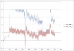
I examined more data in detail today and I am more confused than ever...

STFT01.jpg

STFT02.jpg

(Though I believe the car is more confused than I am.)

But again, at 2500 or so rpms, it looks happy. But the second dataset shows the banks reversed from the first dataset. WTH?
 

markup97

Lost in Translation
That is odd indeed. Looks like a few more datalogs are going to be needed to establish some sort of pattern or some sort of 'average' to go from.
 

driller

El Presidente
Not much progress to report.

I was excited to see the O2 sensors arrived before the weekend but was immediately deflated when I discovered the they were too short! The ones are the car with the Kooks headers measured about 10" so when ordering from Rock Auto I picked a set of Motorcraft ones that were listed with a 10" lead. Not so. They are about 10" counting the length of the sensor and harness plug. A good 4-5" shorter than what I took off the car.

I did discover a part number on the ones I removed, so I searched online and ordered another pair. I'll save the others for spares on the '96.

Meanwhile I hooked up Live Link to the '96 to see what 'normal' STFT's look like. They were pretty spot on bouncing slightly above and below 1.0 with an average of 0.998. They showed good at idle and revs and responded smoothly to a throttle sweep.

At least now I know what they should look like on a datalog. :)
 

markup97

Lost in Translation
So how far out is this car from your other 96?


Having a 'Chinese Blueprint' to go by can be quite helpful when it comes to dialing in a combo.
 

driller

El Presidente
So how far out is this car from your other 96?
Modification-wise, a lot different. It is a 4.6L with stock top end and crank with forged rods and pistons compared to the built up 5.3L with modified heads/cams.

But still, it is a good insight to what the individual PIDs should look like.
 

markup97

Lost in Translation
That is my line of thought, JP. No matter how hard-parts different, it should still require the same basic value scale (in proportion and relation) as a stock unit. At least having the stocker there does give you that 'picture' to look at, the 'Chinese BluePrint' if you will of what the sensors should be doing. Scaling it up/down based on the blueprint should get it close, then fine-tuning should get you dead-on.

I understand theory, but am NOT to the hands-on stage yet. That is why this is nice, as I get to look into both theory and hands-on and make that correlation. I can see what is happening when values change. Thanks for documenting this!
 

driller

El Presidente
Well, another week went by waiting on the correct O2 sensors.

I installed the new O2 sensors, new collector gaskets, JB-Weld smeared all over the collector/tube joints and new spark plugs.

The results are the same. :mad-tilt:

The only thing consistent with the STFT's is when it is about 2500 rpm or more. Then they are pretty spot on. A/F ratio open loop or closed is just about perfect from idle to 3500+ rpms.

What is really odd, there have been a couple times the STFT's are good for a minute or two at idle. Most often it seems bank 1 is approximately 15% more than bank 2 but the odd part is there are times bank 2 is higher than bank 1. I cannot find any vacuum leaks or exhaust leaks.

I'm at a loss. The only thing I know to do is put it on a dyno, load test it and then tune A/F at WOT. :confused-red:
 

driller

El Presidente
Unfortunately not... I've been extremely busy at work and had other matters to attend to.

I may work on it some this weekend. When things settle down I'll get some dyno time arranged.
 
Top