
You are using an out of date browser. It may not display this or other websites correctly.
You should upgrade or use an alternative browser.
You should upgrade or use an alternative browser.
Front airbags over inflate...
- Thread starter mk8fanatic
- Start date
mk8fanatic
Registered
I beleive I have let it air up to high both with the door open and closed...always the same result.....might I add that it never cycles the rear of the car first as it should...it goes directly to inflating the front and does not stop.
mk8fanatic
Registered
Ok guys...I have installed a working suspension ecu or computer from my fathers car that has the air ride delete setup and this mark viii just keeps over inflating.
I have replaced everything with the suspension except the rear ride height sensor. I really dont see how the rear sensor can do this.....any thoughts?
I have replaced everything with the suspension except the rear ride height sensor. I really dont see how the rear sensor can do this.....any thoughts?
mk8fanatic
Registered
Can I possibly use a working front sensor on the rear just to see if it does anything different? Or are the plugs different?
mk8fanatic
Registered
Is there some kind of other power supply to the sensors or the system?
mk8fanatic
Registered
I put a diff sensor on the rear and it still does it.
Can I possibly use a working front sensor on the rear just to see if it does anything different? Or are the plugs different?
I believe the front and rear sensor(s) are different?
I learned a bit about the suspension computer when I installed the ASHAM8 module on my '93. The ASHAM8 module basically intercepts and alters the sensor inputs to the suspension computer. When I was troubleshooting a problem with the module, I was instructed to check the voltages on certain pins. I would have to look for my notes, but basically you want to investigate the voltages on pins 7, 8 and 9 on the suspension module harness connector C204.
Pin 7 is the pink/black wire(LH Front sensor).
Pin 8 is the tan wire(RH Front sensor).
Pin 9 is the orange/black wire(Rear sensor).
Refer to http://members.chello.hu/breda.belarobert/asham8/ASHAM8%20Manual%201st%20ed.pdf for location and identification of the harness connector and pinouts. Use a good digital volt meter. You may also want to check for constant battery power at pins 1 and 21, ignition switched power on pin 4 and a good ground at pin 10.
Perhaps this will help. Right now I'd say you're looking for a possible anomaly in the front sensor voltages compared to the rear.
mk8fanatic
Registered
by anomaly..do you mean a voltage difference? What would you say if there was a drop in voltage...a short somewhere?
Yes, a voltage difference from front to rear is what I would suspect. If I recall, the higher the voltage, the higher the car sits.
Remember the suspension module only knows if the car is high, low or at trim height and commands the solenoids and compressor as needed to raise or lower the car.
I suspect possibly either a short or an open circuit in the front sensor wiring. But I would also suspect either to cause a 'hard fault' and trigger a 'check air suspension' message, but I do not know at what limits such a trigger would occur.
Let's see what the voltages are and go from there.
mk8fanatic
Registered
Sorry to be a pain in the you know what but do I unplug the wiring harness and check them on the plug or on the ecu? Also will the air ride need to be on? because if it does it will air up to a dangerous height and there is no telling when it will stop if at all. Also this car wont do a thing unless the key is turned on or started.
You could pull the 50A compressor fuse in the under-hood fusebox and that should disable the suspension compressor.
Since the ground and voltage feed to the sensors originate from the module, the connectors will need to be plugged in and the air-ride switch will need to be on as well as the ignition will need to be on.
You need to back-probe the connectors. Remember pin 10 will be the sensor ground and pins 7,8 and 9 will be the sensor poitive voltage. Normal height is approximately 2.5 volts. Minimum is 0.5 volts. Maximum is 4.5 volts. Voltage should fluctuate as the corners are bounced.
The only other scenario I envision is the solenoids may open causing the car to drop? Perhaps you could pre-empt that with a jack, lift or jackstands. Regardless, when dealing with a faulty air suspension, expect the unexpected and work safe.
mk8fanatic
Registered
Meter test
Meter test
ok....I borrowed a volt meter and the left front was 1.1 the right front was 1.3 and the rear was 1.6....I also did the test at the plug under the hood by grounding the one wire and It clicked each valve and then vented the pump then the pump came on and that was it......This test is supposed to stop at the problem area and where it stopped was after the pump where the front sensor reading is to take place and vent....In addition now the left front air strut is not rolling on the strut correctly..the one side of the rubber bag is creased and folding inward instead of rolling like it should any advice on how to make it roll again?
Meter test
ok....I borrowed a volt meter and the left front was 1.1 the right front was 1.3 and the rear was 1.6....I also did the test at the plug under the hood by grounding the one wire and It clicked each valve and then vented the pump then the pump came on and that was it......This test is supposed to stop at the problem area and where it stopped was after the pump where the front sensor reading is to take place and vent....In addition now the left front air strut is not rolling on the strut correctly..the one side of the rubber bag is creased and folding inward instead of rolling like it should
any advice on how to make it roll again?mk8fanatic
Registered
My bad I was looking at the wrong scale on the meter for what setting I had it on.......It looks like the front right and left are both sitting at 3.0 and the rear is at a 2.0.....sorry
I was looking at the wrong scale on the meter for what setting I had it on.......It looks like the front right and left are both sitting at 3.0 and the rear is at a 2.0.....sorryIt looks like the front right and left are both sitting at 3.0 and the rear is at a 2.0.....sorry
The voltages appear to reflect exactly what you describe... the front is high.
Assuming the voltages from the sensors are alright, let's back up and diagnose the general system according to the manual(without using the Super Star II Tester).
OA1:"QUICK" WIRING AND CIRCUIT CHECKS
Setup:
- Air suspension switch ON.
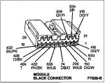
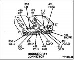
- Control module GRAY connector disconnected.
- Control module BLACK connector disconnected.
Pinpoint tests:
- Module ground - pin 32(-) to battery negative terminal - resistance must be less than 1 ohm.
- Module power - pin 1(+) to pin 32(-) AND pin 21(+) to pin 32(-) - battery voltage.
- Ignition signal - pin 4(+) to pin 32(-) - ignition off = zero / ignition on = battery voltage.
- Door switch signal - pin 5(+) to pin 32(-) - both doors closed = zero / either door open = battery voltage.
- Star Tester Input (STI) line - pin 6(+) to pin 32(-) - voltage = zero / resistance = greater than 1000 ohms.
- Air Suspension Switch - pin 11(+) to pin 32(-) - switch OFF = battery voltage / switch ON = zero.
- Star Tester Output (STO) Line - pin 12(+) to pin 32(-) - ignition OFF = zero voltage / ignition ON = 6.0 volts.
- Spring Solenoids - pins 14/32(Left Front) / pins 15/32(Right Front) / pins 16/32(Left Rear) / pins 17/32(Right Rear) - resistance 14-18 ohms(nominal 16 ohms).
- Compressor Relay Control Line - pin 18(+) to pin 32(-) - battery voltage.
- Vent Solenoid - pin 30 to pin 32 - resistance 19-24 ohms(nominal 21 ohms).
If all the pinpoint tests pass, we can force outputs.
OA2: FORCING OUTPUTS
If the measurements of voltages and resistance have fallen within the given limits, the system output may now be tested. If the voltages and resistance are not within limits, service the faults before continuing.
The following tests are done with the control module black and gray connectors disconnected.
Use a jumper with an in-line fuse rated at not more than 5 amps.
Connect the jumper between the battery supply pin, pin 1 and the individual solenoid pins.
- Left Front - pin 14
- Right Front - pin 15
- Left Rear - pin 16
- Right Rear - pin 17
- Vent solenoid - pin 30
Each solenoid should click as power is applied and should click each time power is removed. A second person listening at the solenoid locations may be necessary.
Connect the jumper between the ground pin, pin 32, and the compressor relay control line at pin 18.
The air suspension system compressor should begin running when ground is applied to pin 18 and it should stop running when the ground is removed.
Patience and persistance will finally prevail.
Attachments
mk8fanatic
Registered
Do you think if I were to buy an ASHAM8 it would able me to trim down the voltage from the front sensors and take back controll of the ride height? Thank you for all your help, I greatly apreitiate it. Oh....I found potentiometers for sale at
http://www.trademotion.com/partlocator/index.cfm?action=searchCatalogOEM&siteid=214290
Just thought I would let ya know
http://www.trademotion.com/partlocator/index.cfm?action=searchCatalogOEM&siteid=214290
Just thought I would let ya know
mk8fanatic
Registered
And enter the part # of course. F7LZ14A605AA
mk8fanatic
Registered
Here is a thought.....what controls the voltage feed to the sensors? There must be some kind of resistor that cuts down the volts to them...no? I mean if the sensor recieved 1 volt to much would it fry the sensor? Or just pass it through as one more volt coming out?
Do you think if I were to buy an ASHAM8 it would able me to trim down the voltage from the front sensors and take back controll of the ride height?
I would not put an ASHAM8 module on any Mark VIII that did not have a properlly functioning suspension system. When I "fine-tuned" the front to rear the adjustment settings had very little range of motion.
Here is a thought.....what controls the voltage feed to the sensors? There must be some kind of resistor that cuts down the volts to them...no? I mean if the sensor recieved 1 volt to much would it fry the sensor? Or just pass it through as one more volt coming out?
Without an internal schematic of the height sensor I couldn't guess. I do know they all share the same power source and ground. If it is a typical voltage divider circuit the output voltage is a % ratio of the input voltage, so an increase in the input voltage would be proportionately divided in the output of the circuit.
I would continue looking for a circuit problem.
mk8fanatic
Registered
So where do you think the power source woul be? fuse box to ECU and the ECU cuts it down? What would you think about using a line resistor that would cut 1/3 or 33.3333333% of 3 volts making it 2 ?