I have a1957 Ford Ranchero that I have installed a 4.6L Four Cam engine and transmission from. I've got almost twelve years in this build and it's finally almost ready. I have an issue with the coil on plug wiring that was changed over from the two coils on the front of the engine from the factory. I ordered and installed a wiring harness that was " supposed to " fit like a glove and it did NOT. Now I'm getting back fires and popping from the exhaust when I get it to run. If you get it revved up to about 2 grand it seems to run okay, but it starts to missfire and run not so good when you bring it down to idle. I'm trying to find a wiring diagram of the coil on plug wiring and I need to compare that to what the harness I bought years ago and make sure that the wires for 1 3 7 2 6 5 4 8 are actually going to the correct coils... Anyone have a diagram or the knowlege to help an old guy get this beast running. It's painted the original colors, Dresden Blue and Colonial White and sports steel wheels with Model A V8 Hubcaps, It has Power Steering, Power Disc Brakes, Power Windows, Power Locks, Cruise Control, Third Brake Light and more and I have renamed this car a RanchCustom with the Lincoln Hood ornament and Tail Gate ornament off a Lincoln MKC. Please HELP me get this straightened out!!!!!
You are using an out of date browser. It may not display this or other websites correctly.
You should upgrade or use an alternative browser.
You should upgrade or use an alternative browser.
4.6l four cam coil on plug wiring diagram
- Thread starter dmkberger
- Start date
I've done this coil pack to COP conversion a couple different ways over the years.
One, simply rewiring the ignition wiring from the coil packs to the COP coils (after removing the coil packs and changing the valve covers) using the original PCM and wiring.
Two, changing from EEC-IV to OBD-2, which was way more involved with swapping the PCM, valve covers and rewiring multiple circuits, including the ignition wiring from the PCM to the COP coils.
I have a crude hand-drawn schematic I followed for the first option, which sounds like what you are seeking. Unfortunately, I am not where I can access the information at this time.
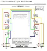
However, it is very much like the following I found via Google...

Pretty sure the R/LG (Red/Light Green) B+ circuit (Battery Voltage) is the same color. According to my notes, the following colors correspond to the coil packs:
Right Coil Pack
T/W - Driver for Ignition Coil 1 (Cylinders 1 & 6)
T/O - Driver for Ignition Coil 2 (Cylinders 3 & 5)
Left Coil Pack
T/LG - Driver for Ignition Coil 3 (Cylinders 4 & 7)
T/LB - Driver for Ignition Coil 4 (Cylinders 2 & 8)
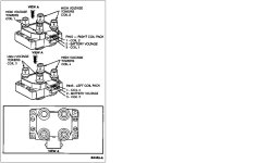
The coil packs and corresponding pin-outs should be as depicted below:

I hope this helps!
One, simply rewiring the ignition wiring from the coil packs to the COP coils (after removing the coil packs and changing the valve covers) using the original PCM and wiring.
Two, changing from EEC-IV to OBD-2, which was way more involved with swapping the PCM, valve covers and rewiring multiple circuits, including the ignition wiring from the PCM to the COP coils.
I have a crude hand-drawn schematic I followed for the first option, which sounds like what you are seeking. Unfortunately, I am not where I can access the information at this time.
However, it is very much like the following I found via Google...

Pretty sure the R/LG (Red/Light Green) B+ circuit (Battery Voltage) is the same color. According to my notes, the following colors correspond to the coil packs:
Right Coil Pack
T/W - Driver for Ignition Coil 1 (Cylinders 1 & 6)
T/O - Driver for Ignition Coil 2 (Cylinders 3 & 5)
Left Coil Pack
T/LG - Driver for Ignition Coil 3 (Cylinders 4 & 7)
T/LB - Driver for Ignition Coil 4 (Cylinders 2 & 8)
The coil packs and corresponding pin-outs should be as depicted below:

I hope this helps!
Thank you for taking the time to help the old guy get this done and make sure it is done correctly! I took the time yesterday to look at the coils and checked from coil to coil with my multimeter and went around going from 1-6 3-5 7-4 and 2-8 but I did NOT understand what the three wires were for on each coil. The diagrams you provided makes it ALL MAKE SENSE NOW!!! May God Bless you!!! Thank you, Thank you, THANK YOU!!! Via con Dios El Presidente

