Hi beams do not work

beerdog

Registered
I am finally trying to diagnose why my hi-beams do not work. I have checked the following.

  1. verified the proper fuse in the fuse panel has power and is good.
  2. verified Fuse 2 in the engine bay junction box is good and receiving and delivering power to the hi-beam relay.
  3. swapped relays around and verified the hi-beam relay is good.
  4. confirmed that the high beam relay does not activate (click) when turning on the high beams.
  5. confirmed the hi-beam relay ground circuits are good using my continuity function on my Fluke.
  6. confirmed there is no power at the 2 hot connections on the relay socket.
  7. the hi-beam indicator turns on/off as expected.
  8. bulbs are good
Clearly I am not getting power to the relay. Any suggestions on what to look at next? I have not done it yet, but I assume the next step is to remove the junction box?
 
That was my first thought, but note #7. the indicator still turning on and off as expected.. I then would have thought relay, but it looks like he's got that covered too.

I'd need to look over the electrical diagram at this point, see where the wires that activate that indicator diverge from the ones that trigger the relay, I suppose.
 
Not necessarily specific in my reply, but in my experience Ford had a history of poor quality headlamps switches through the 80's and 90's. Often it would eventually manifest itself as an overheated harness connector to the headlamp switch, by which time the switch itself would require replacement as the replacement harness could not mate up to the disfigured switch housing.
 
No power at the relay socket is what I had as well. It was on my winter car, so I ended up just wiring in an extra external relay for it. You can trace the bad wire down, but working on that power distribution box is a pain. I was afraid of causing more problems with the other old wires there, as mine happened in winter and I needed the car.
 
are we able to add pictures with this new forum? I seem to have no ability to do so.

The schematics show both inputs to the relay are hot all the time. Would you think the bad wire is in the junction box between from the fuse to the relay?

Does that box come apart? It seems like the upper portion separates from the lower portion to expose the internal wiring. If I wanted to do this do I need to remove all the fuses and relays?
 
are we able to add pictures with this new forum? I seem to have no ability to do so.
Since uploaded attachments occupy server space, that permission is reserved for paid members. Otherwise pictures need to be hosted elsewhere online where you can post them as an external URL. You should see the image icon in the post reply window command line which when clicked will bring up an input window with a space to input the URL of the hosted pic.
 
The schematics show both inputs to the relay are hot all the time. Would you think the bad wire is in the junction box between from the fuse to the relay?

Are you following Pinpoint Test L in the Exterior Lighting Diagnosis and Testing section of the factory manual or simply probing for voltage?
 
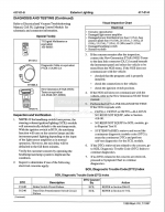
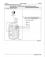
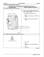
Unfortunately, the PDF service manual will not let you copy/paste. But here are some screenshots...


Screen Shot 2021-05-30 at 12.10.21 PM.png


Screen Shot 2021-05-30 at 12.16.04 PM.png
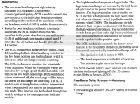
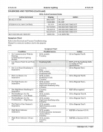
Since the SCIL controls all the lighting, you are supposed to scan the SCIL with the NGS Tester for DTC's as the basis for troubleshooting. If no DTC's related to the concern are retrieved, the Symptom Chart can be reviewed...

Screen Shot 2021-05-30 at 12.21.34 PM.png

As shown, if the High Beams are inoperative, the possible sources include the SCIL module, MultiFunction switch, High Beam Headlamp Relay and Circuitry.

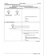
Proceeding to Pinpoint Test L...

Screen Shot 2021-05-30 at 12.26.34 PM.png

Oddly enough, you are supposedly to use the NGS Tester to "command the SCIL" to turn on the headlamps. This is simply because the headlamp switch is nothing more than a PID input to the SCIL module. But lets take a giant leap of faith and assume the SCIL is doing what it is supposed to be doing. If the headlamps do not come on, you are to proceed to L9...

Screen Shot 2021-05-30 at 12.31.49 PM.png

Here you are basically testing for both input and supply power at the relay socket. From your symptom description, you have no power at either pin. So we are to proceed to L13...

Screen Shot 2021-05-30 at 12.35.35 PM.png

Here you are testing Power Distribution Box Fuse 2 (15A). You described that you had power at Fuse 2, so according to the troubleshooting chart, you have an issue with Circuit 12 (LG/BK) that require repair.

Do you have the EVTM for the car? That should show the circuit in question. I would need to look in the paper manual next trip down to the garage. ;)
 
Thanks for the info! I think I have the EVTM. Is that the Green electrical and vacuum manual?
I think the color varies with the year, but yes, the Electrical and Vacuum Troubleshooting Manual will show all the circuits and most pinouts.

If you had a known good SCIL module, I would recommend trying to swap it before tearing into the Power Distribution Box.
 
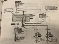
Here is the page from a '97 EVTM...

IMG_7085.jpg

Circuit 12 (LG/BK) is from Fuse 2 to the high beam relay through splice S121.

You could check for continuity from the fuse to the relay. Pull the fuse and the relay, then identify the +12 side of the fuse socket. Check for continuity with an ohmmeter from the OTHER side of the fuse socket to the proper pins of the relay socket.

Note that the SCIL module energizes the relay by grounding the relay coil via pin 25 of the SCIL through circuit 218 (W/P).

The instrument cluster high beam indicator is illuminated separately by voltage from pin 3 of the SCIL through circuit 697 (BR).

I hope this helps.
 
Thanks. I figured out where it is. I think I have this almost figured out. I verified I do not have continuity between Fuse 2 output and relay contacts 2 & 3. This should mean I have a problem in circuit 12 between the relay and the fuse. Likely to be between the fuse and splice 121. Am I I understanding this correctly?
 
That's where my problem was, run a small temporary hot wire to the relay plug to prove it.
 
Back
Top