My passenger's seat wasn't moving forward or backwards properly. It was getting so bad that I had to push it with my hand while pushing the button, to make it move. I figured I better fix it because if the seat won't move at all, it's almost impossible to remove the seat bolts then.
I took photos while I did the work as a sort of "how to" guide for anyone else that might want to do this. I'm not an expert at this, so this should be used as general information only. If anyone sees any errors in this please let me know.
This might not be a do it yourself job for some people, but if you've ever rebuilt a small electric motor before, you should have no problem. I'm an antique model railroader and I've rebuilt many of the electric motors, so that experience probably helped me a bit.
First you need to remove the seat from the car. There are two bolts in the front and 2 nuts in the rear that hold the seat to the floor. You'll need to remove the plastic cover from the bolt and the two covers on the nuts first. You'll need to move the seat forward and back to get to these bolts and nuts. After the bolts and nuts are out, disconnect the seat wire plugs from under the seat.
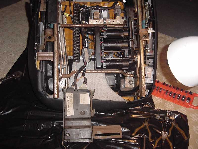
When the seat is out, set it on the floor upside down. I just put 2 new garbage bags on my living room floor and put the seat on them to protect the seat leather.
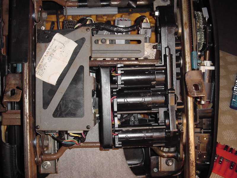
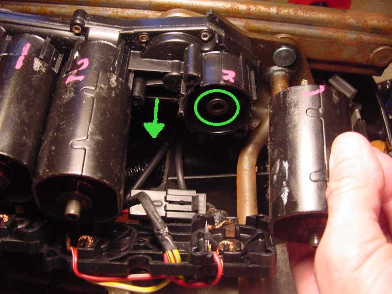
This first photo shows what the bottom looks like. The memory module and bracket for it, is on the left and the 3 motors are on the right.
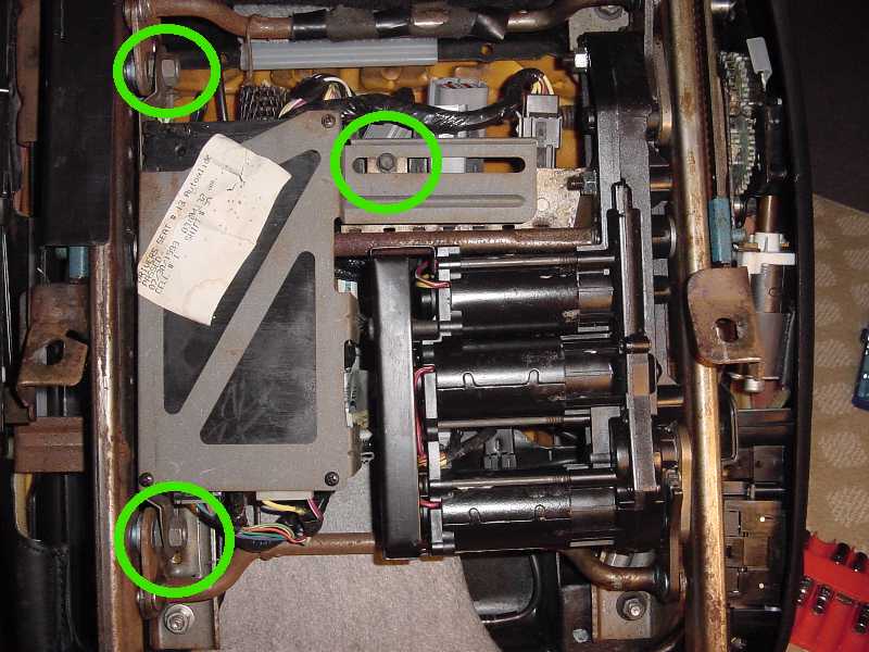
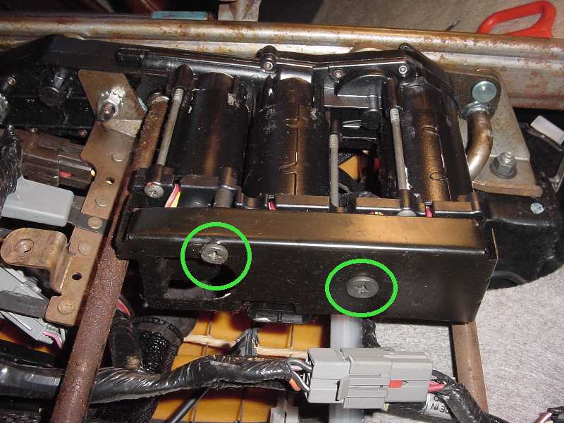
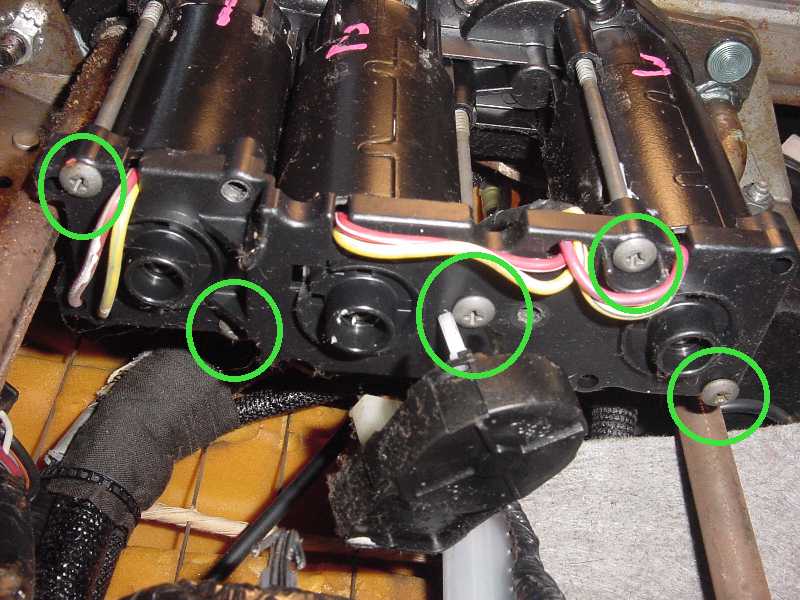
The memory module needs to be removed to access the motors. Remove the 2 nuts and 1 screw circled.
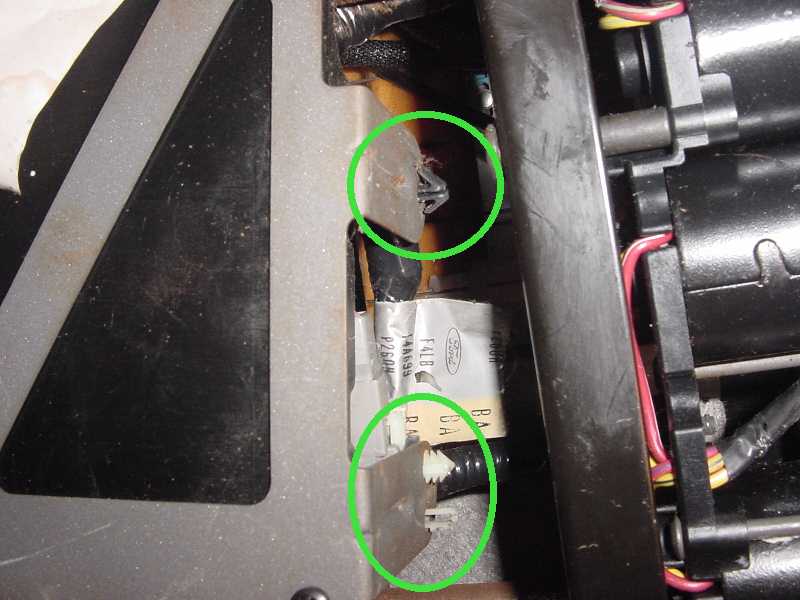
You'll see that some wires are connected to the bracket on the right, with wire hold downs. The black one needs to be compressed with needle nose pliers, then it comes out. The other 2 will come out with a screwdriver or push pin removing tool.
Let the module and bracket hang down as shown in the next photo.
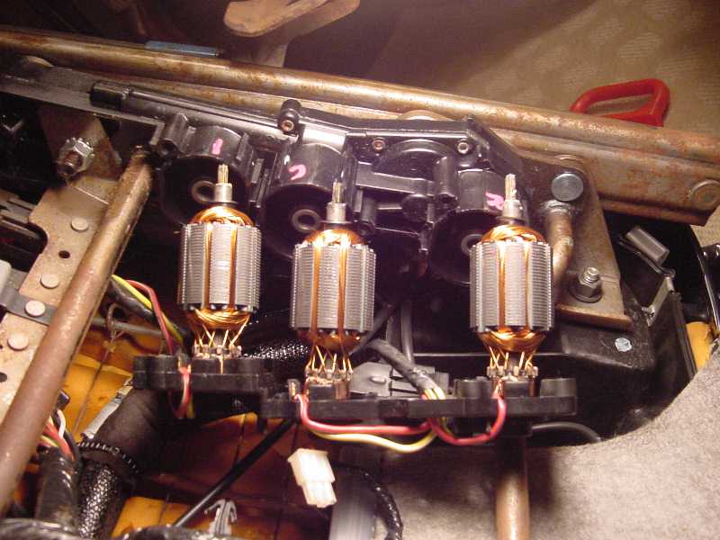
Remove the 2 screws from the cover on the bottom of the motors as shown below and remove the cover.
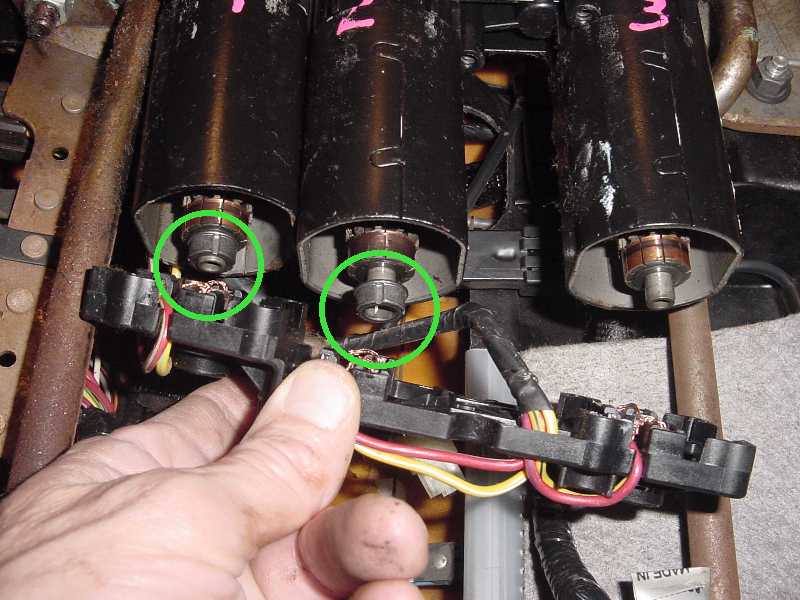
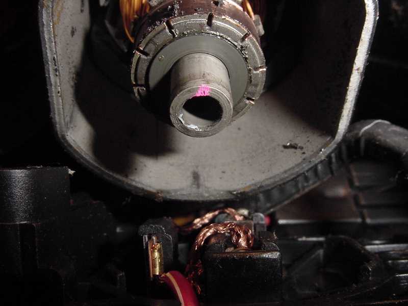
This part on the end of the motor is the encoder or motor position sensor. It is used to tell the memory module what position the motor is in. The passenger's seat only has one sensor and it's used for the Autoglide feature. The driver's seat has sensors on all the motors for the seat position memory feature.
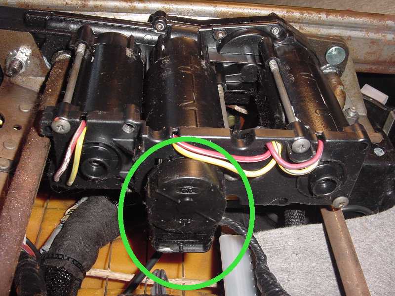
The sensor is removed by using a tiny screwdriver to push in 2 holding latches and gently pulling the sensor out. The photo after this one shows a close up of the latches. Be careful not to rotate the sensor shaft.
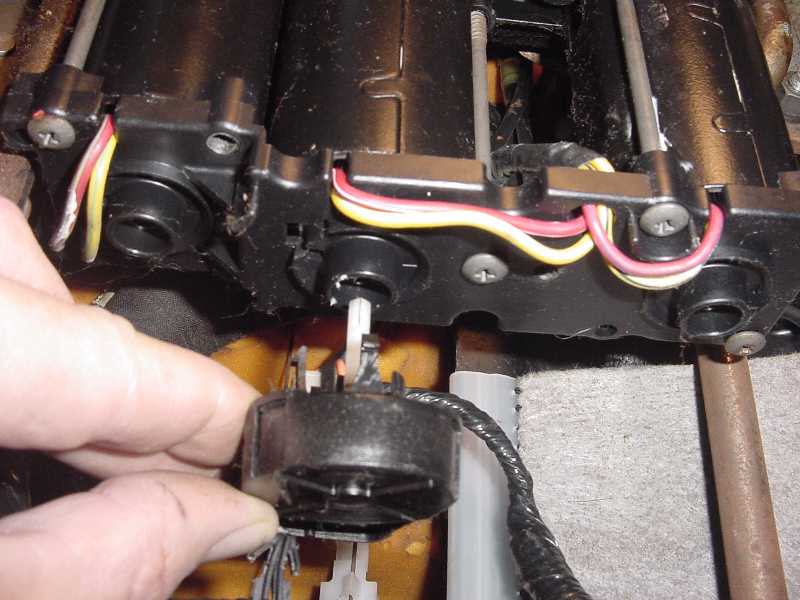
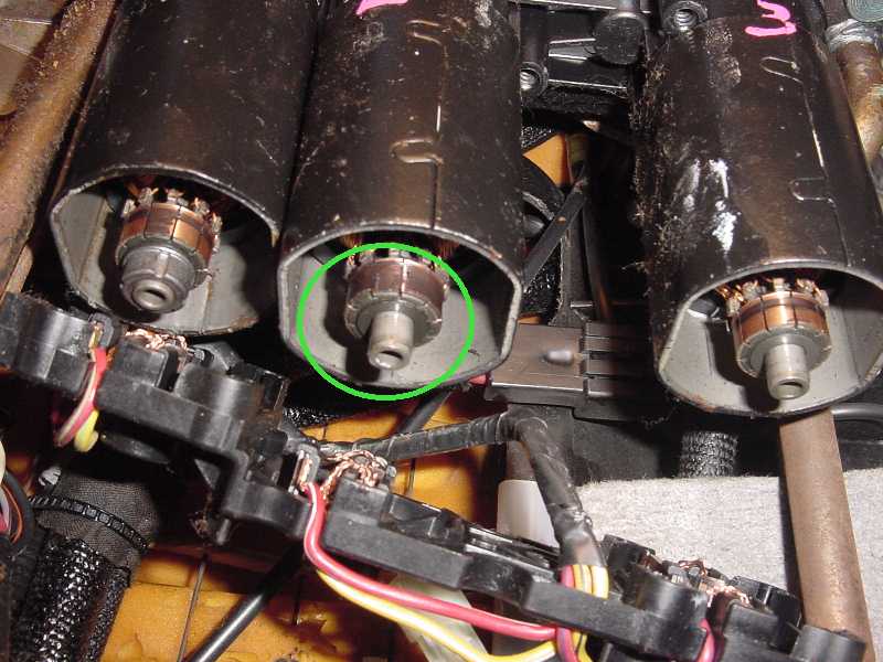
Here is a close up of the 2 holding latches on the sensor. Actually there should be 3 latches on the sensor but one of mine was broke off.

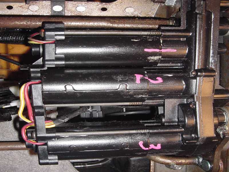
I numbered the motor cases and snouts with a paint pen to make sure that I put them back together correctly.
Next, remove the long bolts holding the motors together.
Next, remove the brush plate. This one peice holds the brushes and armature shaft bushings for all 3 motors. When you remove it you'll hear the little clicks of the brushes coming off of the commutator. Notice the shaft bushings are still on the armature shafts on motor 1 and 2 in this case. If you see this on any of the motors, just pull them the off of the shaft and put them back in the brush plate where they belong for reassembly.
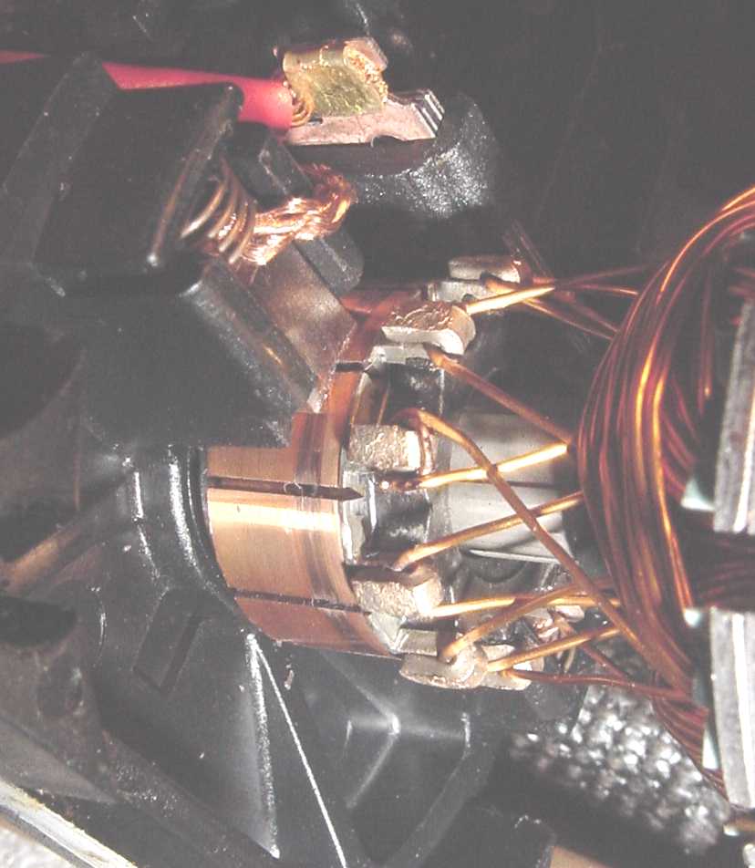
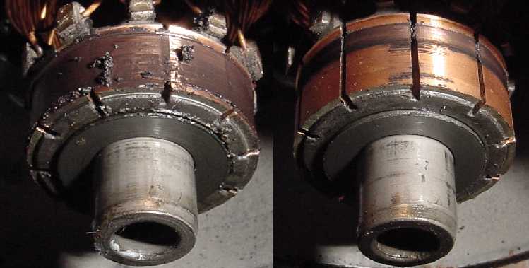
Note how the commutator on motor 2 looks very dirty. This is the motor for the forward and reverse movement of the seat.
Here's a shot comparing the dirty commutator with one of the others , which worked fine. I think I'm onto something here.")
At this point it's important to mark the end of the armature shafts with a paint pen to make sure that they are put back together in the same position. I just marked them on the top at the 12:00 position. This is important for reassembly and to make sure that the position sensor (s) are put together in the original position.
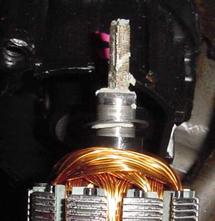
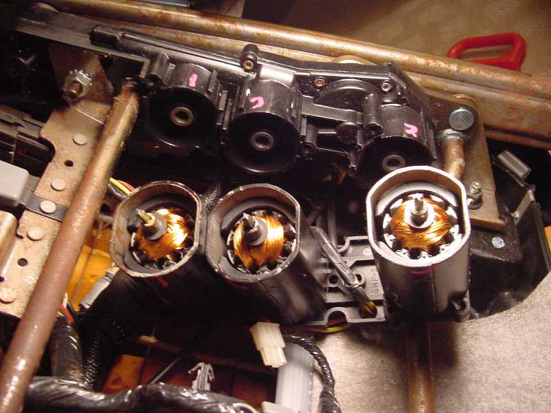
Then remove the motor case and armature by sliding them out in the direction of the arrow. The armature will be stuck to the field magnets in the case. Notice the thrust washer (circled) stuck to the bushing in the motor snout. Just remove it and put it back on the shaft for reassembly.
Here is a photo of the shaft coming out of the motor. The shaft is a square shaped spring. If it slid out, just push it back into the armature.
Remove the other 2 motor cases and armatures. Then work on them one at a time. Don't mix up the parts. Pull the armature out of the case. It will be stuck to the magnets but it will come out. I cleaned the commutators using Q tips and some brake cleaner. I spray a little bit of brake cleaner into the cap and dip the Q tip into it. I was careful to not get the brake cleaner all over everything. I kept cleaning the armature using clean Q tips until the Q tip stayed clean. It's important that the commutators be completley dry before reassembling. I dried them using new Q tips and let them air dry for an hour too.
Once I had all 3 commutators cleaned I cleaned the brushes. I used Q tips here too and cleaned the brushes and the area around them of all the grease. These must be dried completley too.
Once they are all clean and dry, it's time to put the armatures into the bushings in the brush plate.Look at the paint marks that you put on the end of the shaft and make sure that it is in the same position that it was in before. I started with number 1 and worked back to 2 and then 3. You put the shaft into the bushing but the brushes will hold it from going all the way into the bushing. I just used a tiny screwdriver to slide the brushes back away from the commutator while gently lowering the armature into the bushing. It's a little tricky but it will eventually lower all the way and the brushes will be contacting the commutator squarley.
When you have all 3 armatures installed it should look like this.
Then you need to slide the motor cases down around the armatures. The magnets will stick to the armature while doing this so I used one finger inside the case to hold the armature shaft shaft down while I slid the case down. Sorry I don't have photos of this but I needed both of my hands to do this. It's really not difficult and if for some reason the armature pulls out of the brush plate, you can just put it back in.
When you get all 3 cases back on, it should look like this.
Now you're ready to put the motors back together with the motor snouts. First look for your paint marks on the ends of the shaft. You can see them when you tilt the motors/brush plate assembly down to the position where they should be to go into the motor snouts. If the paint marks aren't in the same position that they were before, just turn the armature a bit until they are in the right position.
Just line up the shafts to the bushings in the snouts and push the motor/brush plate assembly in all the way. It should go right together easily. If not, you might need to pull it back out and rotate one or more armatures just a small bit so the square spring shaft lines up to enter the snout.
Once it's together replace the long screws that hold the motors together, and replace the shaft position sensor (sensors if working on the driver's seat). Then replace the rest of the parts in reverse order of dissassembly.
My seat works great now. Hope this helps.
I took photos while I did the work as a sort of "how to" guide for anyone else that might want to do this. I'm not an expert at this, so this should be used as general information only. If anyone sees any errors in this please let me know.
This might not be a do it yourself job for some people, but if you've ever rebuilt a small electric motor before, you should have no problem. I'm an antique model railroader and I've rebuilt many of the electric motors, so that experience probably helped me a bit.
First you need to remove the seat from the car. There are two bolts in the front and 2 nuts in the rear that hold the seat to the floor. You'll need to remove the plastic cover from the bolt and the two covers on the nuts first. You'll need to move the seat forward and back to get to these bolts and nuts. After the bolts and nuts are out, disconnect the seat wire plugs from under the seat.
When the seat is out, set it on the floor upside down. I just put 2 new garbage bags on my living room floor and put the seat on them to protect the seat leather.
This first photo shows what the bottom looks like. The memory module and bracket for it, is on the left and the 3 motors are on the right.
The memory module needs to be removed to access the motors. Remove the 2 nuts and 1 screw circled.
You'll see that some wires are connected to the bracket on the right, with wire hold downs. The black one needs to be compressed with needle nose pliers, then it comes out. The other 2 will come out with a screwdriver or push pin removing tool.
Let the module and bracket hang down as shown in the next photo.
Remove the 2 screws from the cover on the bottom of the motors as shown below and remove the cover.
This part on the end of the motor is the encoder or motor position sensor. It is used to tell the memory module what position the motor is in. The passenger's seat only has one sensor and it's used for the Autoglide feature. The driver's seat has sensors on all the motors for the seat position memory feature.
The sensor is removed by using a tiny screwdriver to push in 2 holding latches and gently pulling the sensor out. The photo after this one shows a close up of the latches. Be careful not to rotate the sensor shaft.
Here is a close up of the 2 holding latches on the sensor. Actually there should be 3 latches on the sensor but one of mine was broke off.
I numbered the motor cases and snouts with a paint pen to make sure that I put them back together correctly.
Next, remove the long bolts holding the motors together.
Next, remove the brush plate. This one peice holds the brushes and armature shaft bushings for all 3 motors. When you remove it you'll hear the little clicks of the brushes coming off of the commutator. Notice the shaft bushings are still on the armature shafts on motor 1 and 2 in this case. If you see this on any of the motors, just pull them the off of the shaft and put them back in the brush plate where they belong for reassembly.
Note how the commutator on motor 2 looks very dirty. This is the motor for the forward and reverse movement of the seat.
Here's a shot comparing the dirty commutator with one of the others , which worked fine. I think I'm onto something here.
At this point it's important to mark the end of the armature shafts with a paint pen to make sure that they are put back together in the same position. I just marked them on the top at the 12:00 position. This is important for reassembly and to make sure that the position sensor (s) are put together in the original position.
Then remove the motor case and armature by sliding them out in the direction of the arrow. The armature will be stuck to the field magnets in the case. Notice the thrust washer (circled) stuck to the bushing in the motor snout. Just remove it and put it back on the shaft for reassembly.
Here is a photo of the shaft coming out of the motor. The shaft is a square shaped spring. If it slid out, just push it back into the armature.
Remove the other 2 motor cases and armatures. Then work on them one at a time. Don't mix up the parts. Pull the armature out of the case. It will be stuck to the magnets but it will come out. I cleaned the commutators using Q tips and some brake cleaner. I spray a little bit of brake cleaner into the cap and dip the Q tip into it. I was careful to not get the brake cleaner all over everything. I kept cleaning the armature using clean Q tips until the Q tip stayed clean. It's important that the commutators be completley dry before reassembling. I dried them using new Q tips and let them air dry for an hour too.
Once I had all 3 commutators cleaned I cleaned the brushes. I used Q tips here too and cleaned the brushes and the area around them of all the grease. These must be dried completley too.
Once they are all clean and dry, it's time to put the armatures into the bushings in the brush plate.Look at the paint marks that you put on the end of the shaft and make sure that it is in the same position that it was in before. I started with number 1 and worked back to 2 and then 3. You put the shaft into the bushing but the brushes will hold it from going all the way into the bushing. I just used a tiny screwdriver to slide the brushes back away from the commutator while gently lowering the armature into the bushing. It's a little tricky but it will eventually lower all the way and the brushes will be contacting the commutator squarley.
When you have all 3 armatures installed it should look like this.
Then you need to slide the motor cases down around the armatures. The magnets will stick to the armature while doing this so I used one finger inside the case to hold the armature shaft shaft down while I slid the case down. Sorry I don't have photos of this but I needed both of my hands to do this. It's really not difficult and if for some reason the armature pulls out of the brush plate, you can just put it back in.
When you get all 3 cases back on, it should look like this.
Now you're ready to put the motors back together with the motor snouts. First look for your paint marks on the ends of the shaft. You can see them when you tilt the motors/brush plate assembly down to the position where they should be to go into the motor snouts. If the paint marks aren't in the same position that they were before, just turn the armature a bit until they are in the right position.
Just line up the shafts to the bushings in the snouts and push the motor/brush plate assembly in all the way. It should go right together easily. If not, you might need to pull it back out and rotate one or more armatures just a small bit so the square spring shaft lines up to enter the snout.
Once it's together replace the long screws that hold the motors together, and replace the shaft position sensor (sensors if working on the driver's seat). Then replace the rest of the parts in reverse order of dissassembly.
My seat works great now. Hope this helps.
Last edited: